
When simulating flow in porous media, it can be efficient to simplify the geometric complexity of the real porous material using a homogenized macroscale approach. But what if we don’t know what the effective macroscopic properties are? Here, we look at how to extract the macroscopic flow properties of porosity and permeability from a fully resolved microscale submodel.
Using a Macroscale Approach to Model Porous Media Flow
In a previous blog post, we discuss interfaces available for simulating macroscale flow in porous media, including the Darcy’s Law interface. Solving for Darcy’s law can provide insight into many different physical systems where it is practically impossible to simulate the fully resolved microscale system. This difficulty is due to the large difference between the length scales of the microscopic and macroscopic systems found in application areas such as oil and gas, civil engineering, and biological and medical engineering.
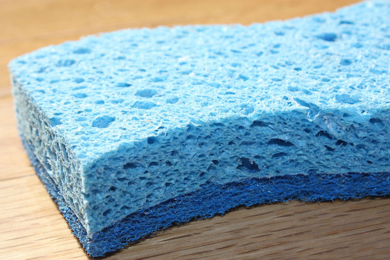
A sponge is one example of a porous material.
The macroscale approach assumes that the behavior of the pore space is quantified by two averaged quantities:
- Permeability
- Porosity
Permeability characterizes the resistance to flow through the pores. Porosity, which is defined as the volume fraction of the pore space, determines the superficial average velocity. As for the superficial velocity, it is the equivalent velocity through the homogenized domain — as if the microscopic flow through the pore space were distributed evenly at the macroscopic scale.
If the porosity and permeability are not known, experimental results are necessary to quantify these material properties. Numerical experiments via simulation can also be used to analyze the fully resolved geometry, which includes voids and solid particles. By solving the Navier-Stokes equations (or its linear approximation for small Reynolds numbers, called Stokes flow or creeping flow) on the microscale geometry, the porosity and permeability of the porous medium can be extracted.
Creating a Microscale Porous Geometry
Before we investigate the porosity and permeability of a porous medium, we must discuss the generation of the microscale geometry. This is not necessarily a simple process! Creating such a geometry often requires specialized third-party software (like Simpleware or Mimics®) to reconstruct scanned image data, particularly for complex 3D geometries. Here, we focus on a 2D cross section, such as one generated from a scanning electron microscope (SEM) image.
The Pore-Scale Flow tutorial model is created from an image file that is directly imported into the COMSOL Multiphysics® software as a function. The geometry is reconstructed from this function by using methods similar to those discussed in the following blog posts:
- How to Use Topology Optimization Results as Model Geometries
- Modeling Irregular Shapes: How to Import Curve Data and Loft a Solid
For geometries that are too complex or contain restrictively small features that impact the mesh resolution, you can use the approach adopted in the pore-scale flow tutorial, which will be discussed in an upcoming blog post.
Using the Creeping Flow Interface in COMSOL Multiphysics®
Let’s now take a quick look at the pore-scale flow example, which solves the fully resolved pore space geometry. We can use the postprocessing tools within COMSOL Multiphysics to extract the porosity and compute the permeability by using Darcy’s law.
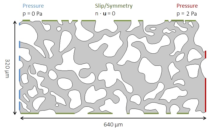
The dimensions of the whole geometry are 640 × 320 μm (and the channel width in the pore spaces is even narrower), so we know the characteristic length scale, L, is small. Further, as we are considering a slow flow driven by a pressure gradient of 2 Pa, we also know that the typical velocity, U, is low. Therefore, given a water-like fluid with a density of ρ = 1000 kg/m3 and viscosity of μ = 0.001 Pa*s, we can safely neglect the inertial term of the Navier-Stokes equations and solve using the Creeping Flow interface. We can use this interface because the Reynolds number, Re, is significantly less than 1.
Get more information in this blog post: Characterizing the Flow and Choosing the Right Interface
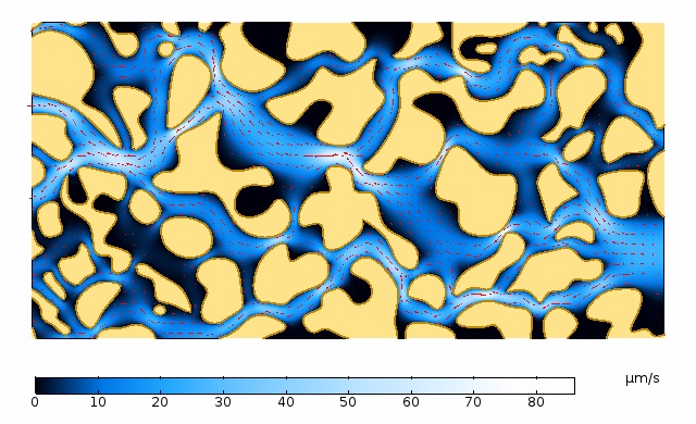
The pressure drop is applied from right to left using Inlet and Outlet conditions. As this model is a representative cross section of the porous medium that we wish to characterize, a Symmetry condition is prescribed along the boundaries caused by the truncation of the geometry at the top and bottom. These boundaries are indicated in the left figure below. The image on the right shows the results, visualized using a velocity magnitude color plot with arrow vectors of the flow direction.
Left: Geometry and boundary conditions of the fully resolved microscale model solved with the Creeping Flow interface. Right: Velocity magnitude color plot with a red arrow plot representing the orientation of the flow through the pore space.
Computing the Porosity and Permeability of the Porous Medium
Calculating Porosity
We first compute the porosity, por. In this 2D example, we need to calculate both the total area and the area represented by our computational domain.
We can compute the total area simply as a variable: A_tot = L*H. To determine the area of the pore space, A_por, we can integrate the expression “(1)” over the flow domain. This can be easily achieved by using an integration component coupling, a custom operator that can integrate any expression over domains, boundaries, and more. The settings used for the computation of A_tot, A_por, and por are shown in the image below.
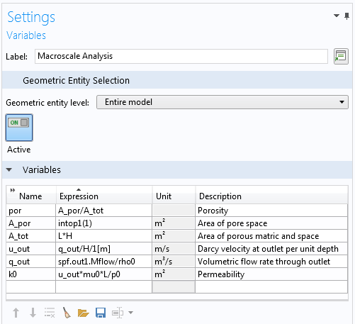
Definitions of variables used in computing the porosity and permeability.
Calculating Permeability
The image above also shows how the permeability, k0, is computed. Darcy’s law states:
where u is the Darcy or superficial velocity, κ is the permeability, μ is the dynamic viscosity, and ∇p is the pressure gradient.
The Darcy velocity can be computed with some help from the predefined variables within the Creeping Flow interface.
The variable spf.out1.Mflow defines the mass flow through the outlet boundary, where we can divide by the constant density, ρ0, to obtain the volumetric flow rate. This can then be divided by the height of the porous medium and again by 1 m, to account for the 2D approximation and obtain the Darcy velocity in the x direction.
By rearranging (1) and substituting \nabla p = \frac{\Delta p}{L}, we can use the known pressure drop, p0, across the length of the porous region, L, to evaluate the permeability to the variable k0.
The results show us that this microscale representation of the porous medium has a porosity of 0.553 and a permeability of 4.59 × 10⁻¹² m2.
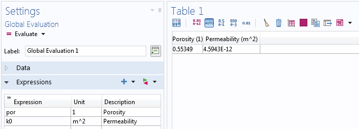
Results table for the computed porosity and permeability from the fully resolved flow submodel.
Concluding Thoughts on Computing Porosity and Permeability
In this blog post, we discussed how we can use simulation to derive the macroscale properties of flow through porous media — solving a free flow problem on a fully resolved microscale submodel. Equipped with this information, we can use these parameters as input for a more descriptive macroscale model. Better still, this approach is the ideal way to know what input to use in a user-friendly app, such as in this example app that considers the productivity and safety of a perforated well.
Additional Resources
- Read this blog post to learn how to model heterogeneous catalysis
- Check out this tutorial on simulating the effective diffusivity in porous materials



Comments (15)
Yu Zhang
August 17, 2018Hi, Andrew Young:
Thank you for sharing us this useful technique. I encountered a convergence issue caused by the extremely small permeability which can reach 1e-21[m^2]. I have tried many ways, but it is still there. Do you have any experiences about how to solve it? Any response and help will be highly appreciated.
Best regards,
Yu
Andrew Young
August 21, 2018 COMSOL EmployeeHi Yu,
Thanks for reading the blog and for your comment!
For questions related to your modeling, please contact our Support team:
– Online Support Center: https://www.comsol.com/support
– Email: support@comsol.com
Best regards,
Andrew
Vikash Kumar
February 2, 2021Hi Andrew
I want to simulate a transient three-phase flow in porous media considering capillary action. The porous zone is initially filled with air. I want to model the displacement of air with two liquid (water and glycerin, let’s say) due to capillary forces. My main interest is the degree of wetting and the spreading of the wetting front. How to model capillary effects in the porous zone?
I did a two-phase simulation, but for the three-phase I need UDFs. I saw your video and found it helpful. Could you please share the momentum source term code for the capillary rise? In addition, how to write UDFs to simulate the three-phase flow in porous media.
Dey
September 7, 2018Hi Andrew Young,
Thank you for sharing with us, I am using the same example of pore scale model but doing the coupling with the heat transfer in porous media and solid mechanics, i need help in how to handle the 3 physics together, i can just couple 2……..any idea in how to do it,?
Andrew Young
September 11, 2018 COMSOL EmployeeHi Telma,
My thanks to you also for your feedback! It is certainly possible to extend the concept of this blog to include heat transfer and fluid-structure interaction (i.e. Solid Mechanics in the matrix and fluid flow in the pore space). This will depend upon the detail with which you wish to model the interactions. For more information, please contact our Support team as mentioned in my previous comment.
Thanks again,
Andrew
TOUSSAINT DONO NGARTA
December 13, 2018Hi Telma,
I think we’re working on the same thing. If you can leave me your e-mail and we’ll discuss it more.
Thank you!
telma abibo
March 1, 2019Hi Toussant abibotelma@gmail.com
Nabila Shamim
March 6, 2019Hello do you have a tutorial to show how to make the geometry of the porous media.
telma abibo
March 9, 2019Nabila Shamin, you can import the geometry, it’s available in the application subsurface flow-pore-scale
telma abibo
March 9, 2019Andrew Young I did the T-H-M for the case and I used the Brinkman interface for porous media which is not suitable for the discrete model, where fluid flow through channels of pores and the rigid solid does not allow fluid flow, do you have any idea of which interface should i use between the “free and porous media or laminar? Help
Brianne Christopher
March 11, 2019 COMSOL EmployeeHello Telma and Nabila,
Thank you for your comments.
For questions related to your modeling, please contact our Support team.
Online Support Center: https://www.comsol.com/support
Email: support@comsol.com
Supriya Yadav
May 29, 2019Andrew young can you please tell me which model i used for my work in microfluidics . means if we take water as a liquid and flow it to a microchannel using filter paper.Any response and help will be highly appreciated. and i m extremely waiting for your suggestions .
桂杰 桑
May 16, 2020Hi Andrew, nice work! Are there any relevant publications or citable sources for this work? For example, scholars may want to cite this idea and publish something in the future.
Vikash Kumar
February 2, 2021Hi Andrew
I want to simulate a transient three-phase flow in porous media considering capillary action. The porous zone is initially filled with air. I want to model the displacement of air with two liquid (water and glycerin, let’s say) due to capillary forces. My main interest is the degree of wetting and the spreading of the wetting front. How to model capillary effects in the porous zone?
I did a two-phase simulation, but for the three-phase I need UDFs. I saw your video and found it helpful. Could you please share the momentum source term code for the capillary rise? In addition, how to write UDFs to simulate the three-phase flow in porous media.
Виктор Александрович Пичугов
April 13, 2022Good afternoon, Andrey Young. My name is Viktor Pichugov, I am studying at a Russian university on a bachelor’s degree program. Now I am doing a thesis, the topic of which is related to your work. Can I list you and your article as supporting material?
Thank you in advance for the answer