
A team of medical physicists at the Cross Cancer Institute in Alberta, Canada has come up with an innovative approach to treat cancer. In affiliation with The Linac-MR Project, the team led by Gino Fallone aims to improve the accuracy of cancer treatment by reducing damage to healthy tissue surrounding a tumor site, while ensuring the tumor receives the intended radiation dose. They are accomplishing this through the development of a hybrid linear particle accelerator (Linac) integrated with magnetic resonance imaging (MRI). The hybrid Linac-MR system is designed for real-time image-guided tumor tracking that can detect and compensate for motion of the body during treatment. It’s obviously a terrific idea because it vastly improves the efficacy of treatment for patients. How do they make it work?
Design Challenges for the Linac-MR Project Team
The development of the hybrid Linac-MR system comes with a very unique set of challenges that were explained by Fallone in the article “MRI Tumor-Tracked Cancer Treatment” appearing on page 18 in the 2013 edition of COMSOL News. In order to meet their objectives, the team designed an MRI system, a Linac for radiotherapy, and then determined the optimal hybridized configuration. The design of the room that houses the hybrid Linac-MR system was also an important consideration since it must shield operators and other equipment from x-rays and electromagnetic fields coming from the Linac and MRI systems.
“It would be difficult to overstate the different engineering and physics issues within the Linac-MR Project” says Fallone in the COMSOL News article. Integrating the two systems requires an in-depth understanding of how one system affects the performance of the other. The Linac incorporates an RF waveguide that accelerates electrons toward a target with a high atomic number to produce the x-rays required to destroy tumor cells. RF generated by the Linac interferes with the detection of weak RF signals required by the MRI system to construct a 3-dimensional image with excellent soft tissue contrast. In addition, the magnetic field from MRI is strong and interferes with Linac operation by deflecting the electron beam, causing it to miss the target.
Magnetostatic and Electromagnetic Simulation
To overcome these challenges, the team has used COMSOL Multiphysics to better understand the physical effects that degrade the performance of the Linac-MR system. Magnetostatic simulations were important in the design of shielding to protect the Linac and prevent the degradation of image quality from MRI. At first, the shield was a 5 cm thick steel plate that measured 200 cm by 200 cm. Using simulation, they were able to reduce the shield to a 30 cm radius and 6 cm thickness resulting in a weight that is approximately one-third of the original value.
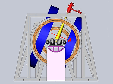
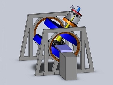
Simulation proved invaluable in optimizing the geometry of the hybridized Linac-MR system. Designs where the MR scanner could move in the transverse and longitudinal directions, shown in the figures below, were proposed and evaluated.
|
|
| Transverse rotating biplanar geometry. | Longitudinal rotating biplanar geometry. |
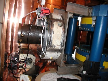
Initially, the transverse geometry complete with circular shield was built and tested as shown in the following images.

|
|
| Front-view of the Linac system. | Side-view of the Linac system. |
Simulation and experiments were performed to investigate angle-specific field variations that could reduce image quality. To do this, the Linac system was rotated around the MR scanner. Fallone and his team found that mounting the Linac system and MR scanner onto the same gantry would allow them to move together and reduce distortion in the field. This unified configuration is referred to as a rotating biplanar geometry.
The longitudinal geometry variation, however, requires a hole in the center of the magnet for x-rays to pass through. This can lead to field inhomogeneity that was evaluated and optimized using simulation.
Another interesting and important detail they had to consider was the design of the Linac system. Their plan calls for a system capable of producing a 10 MeV electron beam. Initially, they estimated that a 70 cm long waveguide would be required. However, simulation results (shown in the figures below) revealed that a 30 cm waveguide would be sufficient. The smaller waveguide means that they can build a smaller room for the Linac-MR, further reducing the room shielding costs.
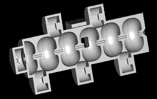
Cutaway view of the Linac system waveguide with RF cavities.
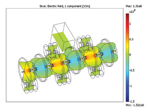
Electromagnetic field distribution in a short 10 MeV waveguide.
Milestones for the Linac-MR Project
The Linac-MR Project team has already met, and is on its way to achieve, some very significant milestones. The project began in 2005, and after only three years they presented the first working prototype of a transverse Linac-MR. By 2016, they expect to have a whole-body Linac-MR in public use.
Further Reading
- Catch the full article on page 18 of COMSOL News 2013, “MRI Tumor-Tracked Cancer Treatment”


Comments (1)
Abdullah Afzal
October 5, 2024how the Geometry of linac mri working can I get the link to see the simulation of this model to analyze the output