Aggiornamenti MEMS Module
Nuova formulazione per l'elettrostatica
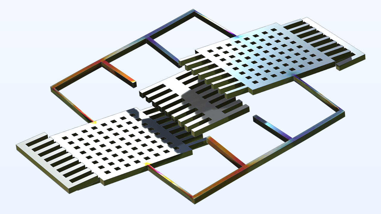
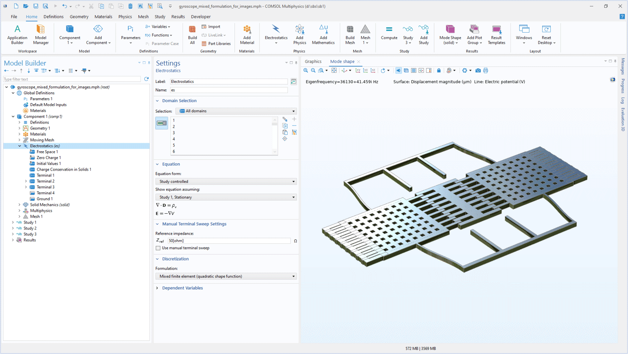
Per l'analisi elettrostatica, una nuova formulazione delle equazioni offre calcoli più accurati della forza elettrostatica, particolarmente utili nella modellazione di dispositivi MEMS come accelerometri e giroscopi. Risolvendo direttamente il flusso del campo elettrico di spostamento, questo approccio migliora l'accuratezza nelle geometrie con angoli vivi, consentendo valutazioni più pratiche della forza. A differenza della formulazione tradizionale basata sul potenziale, il nuovo metodo utilizza una tecnica di formulazione mista, risolvendo due equazioni: una per il campo di spostamento elettrico (D) e un'altra per il potenziale elettrico (V), con quest'ultima che funge da vincolo. Questa formulazione D-V, denominata Mixed finite element, è disponibile sia per la modellazione 2D che 3D ed è l'opzione di discretizzazione predefinita per l'interfaccia Electrostatics utilizzata con l'interfaccia multifisica Electromechanics.
Nuove interfacce multifisiche di elettromeccanica
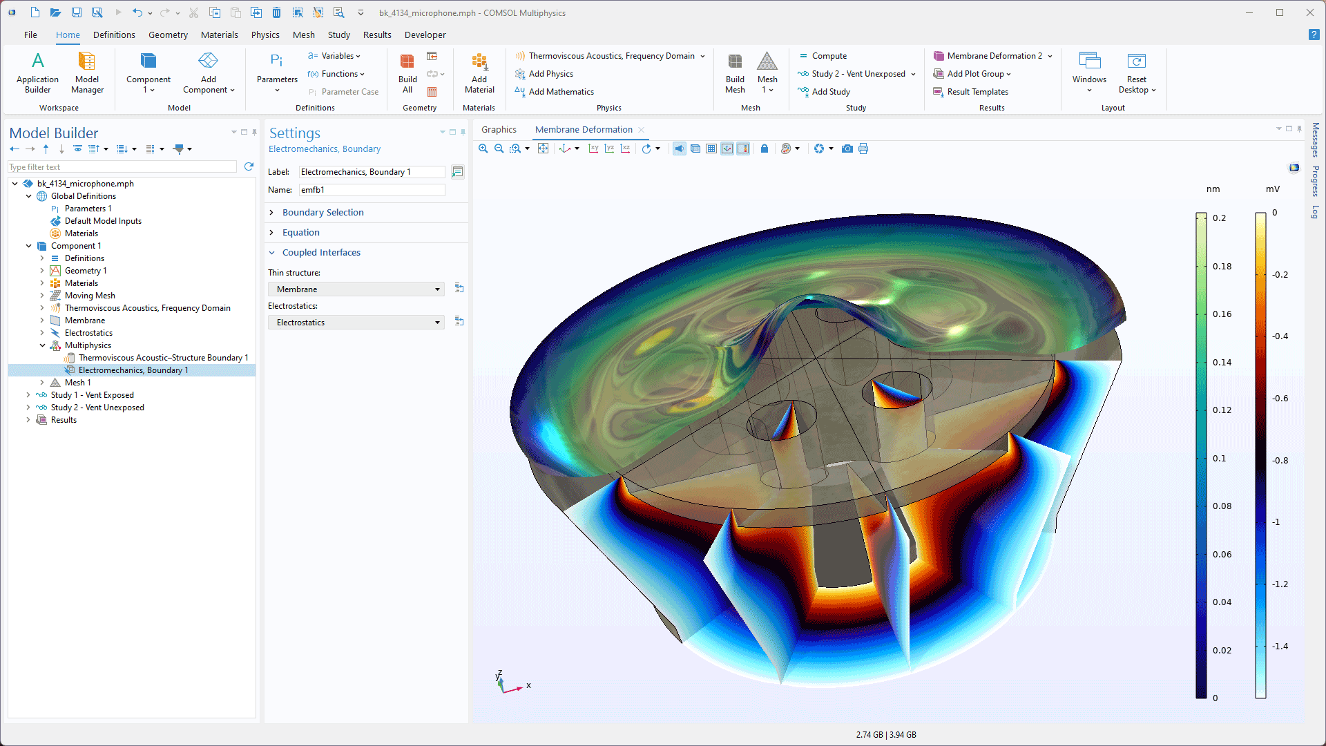
Le nuove interfacce Electromechanics, Shell ed Electromechanics, Membrane semplificano la modellazione della deformazione di strutture sottili, come le membrane microfoniche, influenzate da forze elettrostatiche. Queste interfacce includono automaticamente l'accoppiamento multifisico Electromechanics, Boundary per una perfetta integrazione con elementi shell o membrana e utilizzano l'interfaccia Electrostatics per modellare il campo elettrico. Dimostrate nei tutorial Brüel & Kjær 4134 Condenser Microphone e Axisymmetric Condenser Microphone, queste interfacce richiedono anche lo Structural Mechanics Module.
Accoppiamento multifisico di ritiro e rigonfiamento
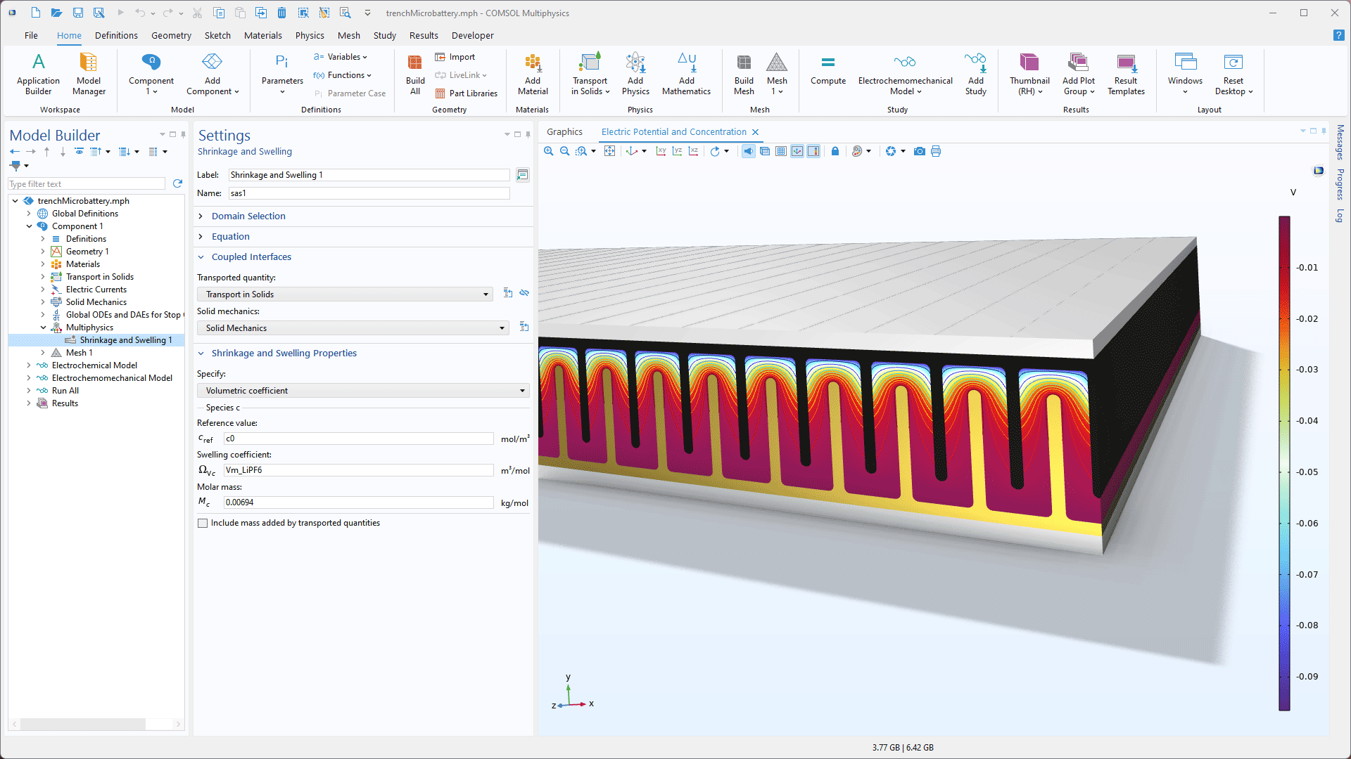
Per modellare le variazioni di volume indotte dalla diffusione, è stato aggiunto un nuovo accoppiamento multifisico Shrinkage and Swelling che collega bidirezionalmente le interfacce Transport in Solids e Solid Mechanics. Questo nuovo accoppiamento può essere utilizzato per simulare gli effetti delle variazioni di concentrazione sul volume e studiare come le sollecitazioni possono influenzare la diffusione. Ciò è utile, ad esempio, nelle batterie, dove possono verificarsi variazioni di volume molto grandi a causa del trasporto degli ioni.
Formulazione del contatto per i contorni interni
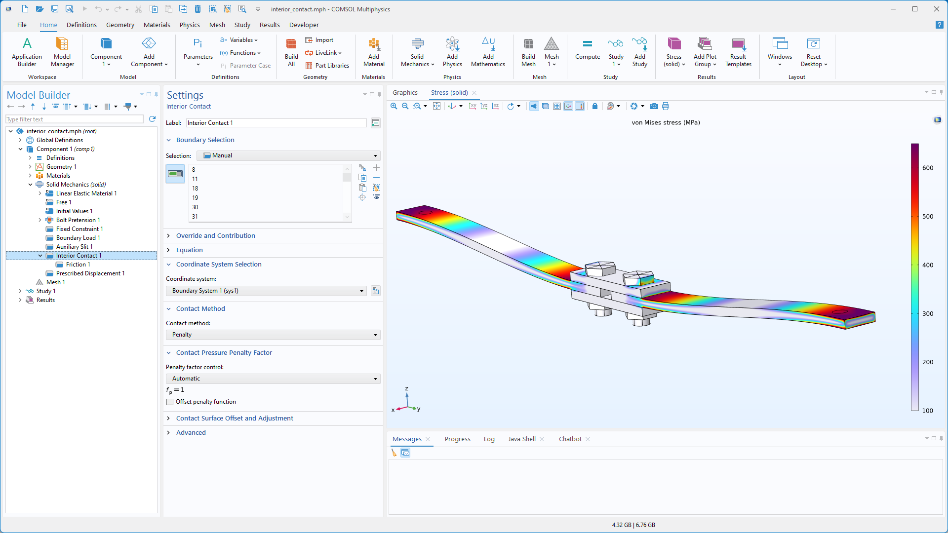
All'interfaccia Solid Mechanics è stata aggiunta una nuova funzione Interior Contact che consente di includere condizioni di contatto come attrito, adesione e decoesione ai contorni interni. Con questa formulazione, le coppie di contatto e gli assiemi non sono necessari e l'analisi può essere geometricamente lineare. Questa funzione può essere utilizzata per la modellazione di applicazioni quali giunti bullonati e contorni separati dalla decoesione.
Nuova funzione predefinita Free Space
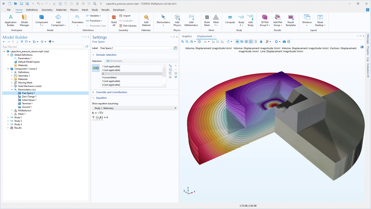
All'interfaccia Electrostatics è stata aggiunta una nuova funzione predefinita, Free Space. Questa caratteristica definisce le condizioni fisiche vicino al dispositivo modellato, tipicamente in aria o nel vuoto. La funzione serve come punto di partenza per ulteriori affinamenti, consentendo di aggiungere altre funzioni, come Charge Conservation in Solids, per specificare localmente le proprietà dei materiali e i metodi di eccitazione.
Cartella della libreria dei materiali compositi
La nuova cartella integrata per Composites è suddivisa in tre gruppi di materiali: costituenti in fibra, costituenti in matrice e lamine. Questa funzionalità facilita la creazione di modelli con i tipi più comuni di lamine composite.
Nuovi tutorial
La versione 6.3 di COMSOL Multiphysics® introduce due nuovi tutorial nel MEMS Module.
Micromachined Gyroscope with Mixed Formulation
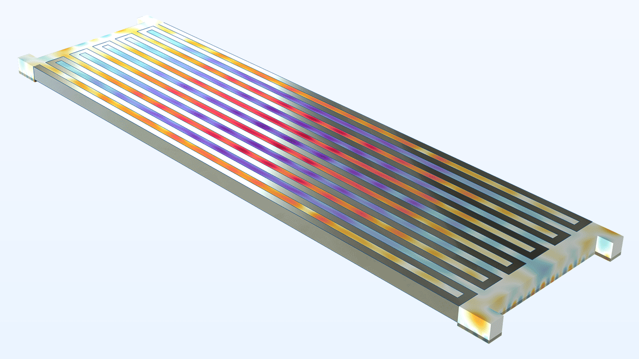
Aluminum Nitride Lamb Wave Resonator — Layered Shell Version*
Titolo in Application Library:
aln_lamb_wave_resonator_layered
Download da Application Gallery
*Richiede Composite Materials Module

