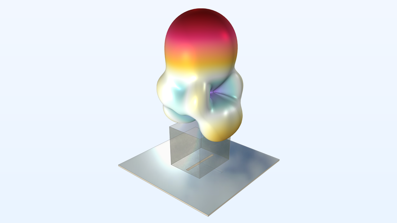
Aggiornamenti RF Module
Nuova interfaccia multifisica predefinita per l'analisi dei parametri delle linee di trasmissione
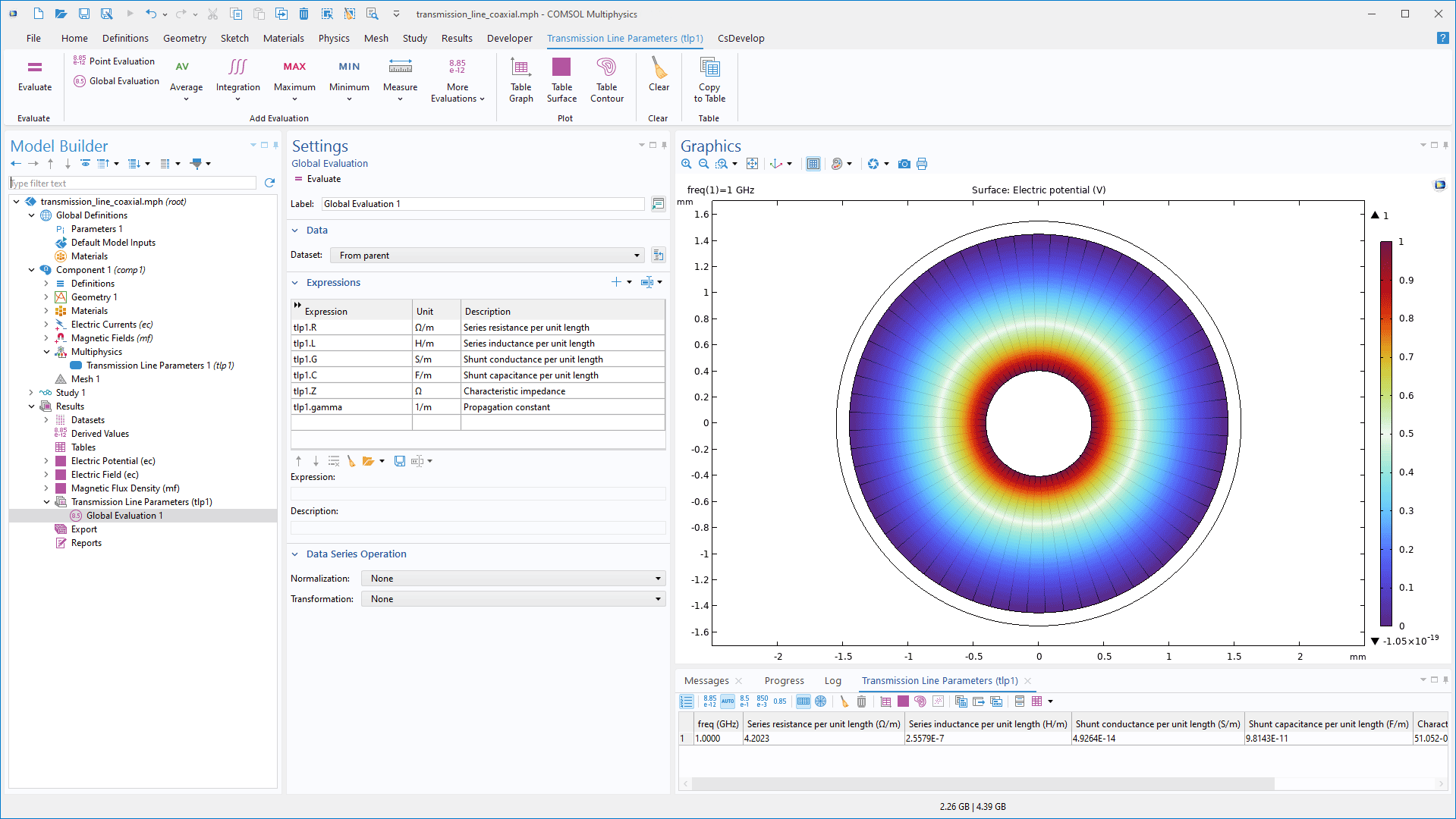
La nuova interfaccia Transmission Line, RLGC Parameters è utilizzata per calcolare i parametri delle linee di trasmissione multiconduttore, tra cui la resistenza in serie, l'induttanza, la conduttanza shunt e la capacità per unità di lunghezza, nonché l'impedenza caratteristica e la costante di propagazione. Questa interfaccia combina le interfacce Electric Currents e Magnetic Fields per la modellazione nel dominio della frequenza, supportando l'analisi 2D delle sezioni trasversali delle linee di trasmissione. Il nuovo tutorial Transmission Line Parameters of a Coaxial Cable mostra questa interfaccia.
Nuovo grafico predefinito per una visualizzazione più intuitiva
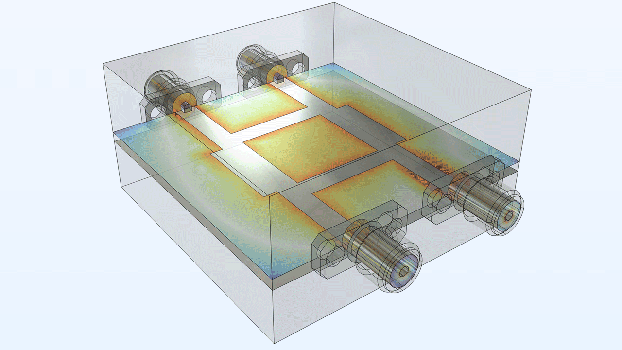
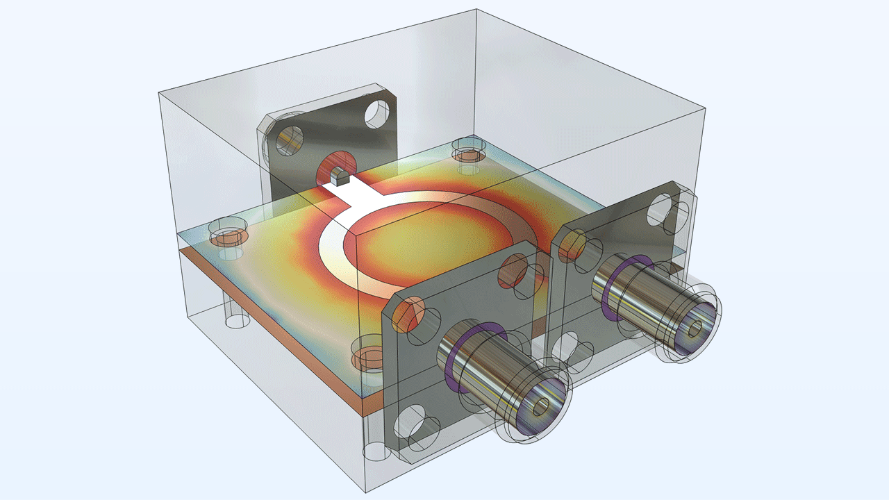
All'interfaccia Electromagnetic Waves, Frequency Domain è stato aggiunto un nuovo grafico predefinito, Electric Field, Logarithmic. Questo grafico si basa sulle caratteristiche delle proprietà fisiche e delle selezioni del modello e utilizza una scala logaritmica per fornire una visualizzazione più intuitiva del decadimento dell'intensità del campo. Inoltre, enfatizza le superfici conduttive attraverso una prospettiva che migliora la percezione 3D. Tutti i tutorial 3D calcolati con l'interfaccia Electromagnetic Waves, Frequency Domain e lo studio Frequency Domain sono stati aggiornati per mostrare questo nuovo grafico.
I nuovi grafici predefiniti di un tutorial di accoppiatore di rami e di un tutorial di divisore di potenza Wilkinson.
Quantificazione dell'incertezza dei componenti a microonde
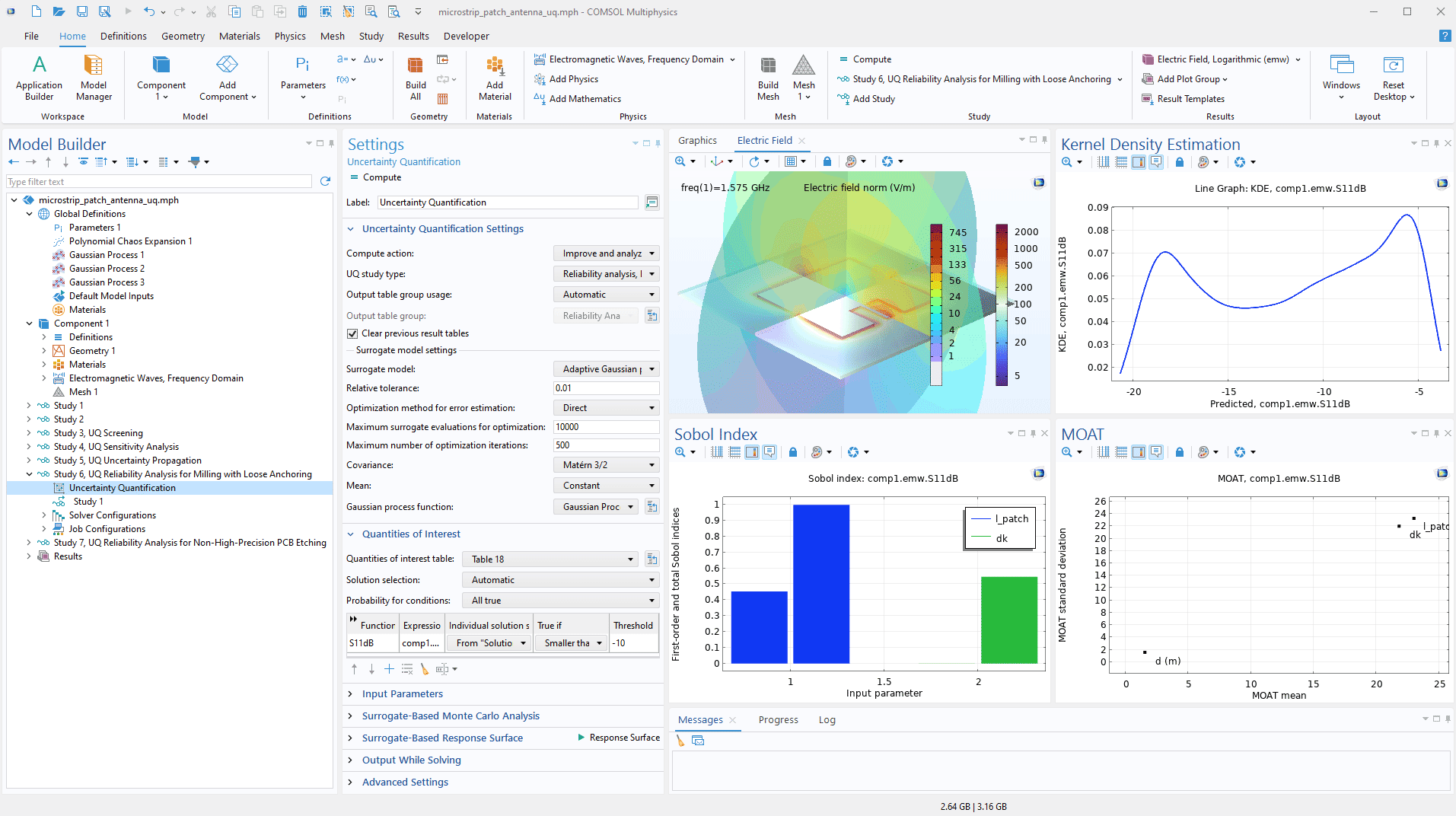
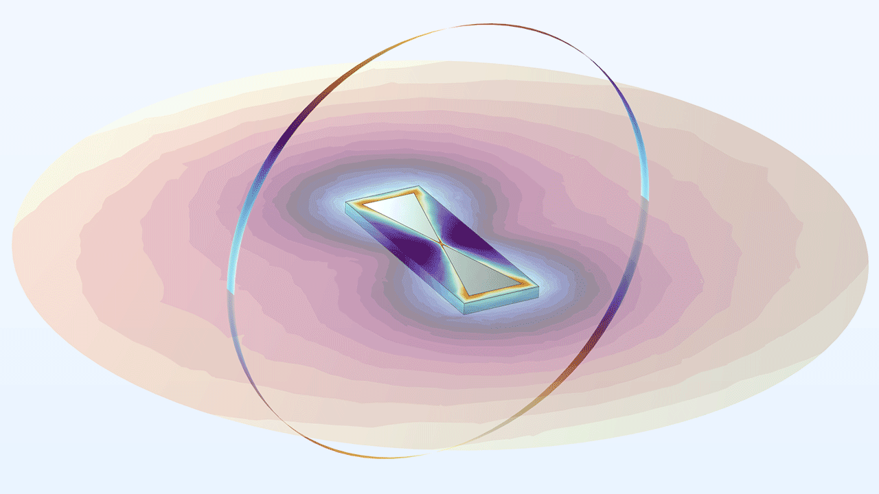
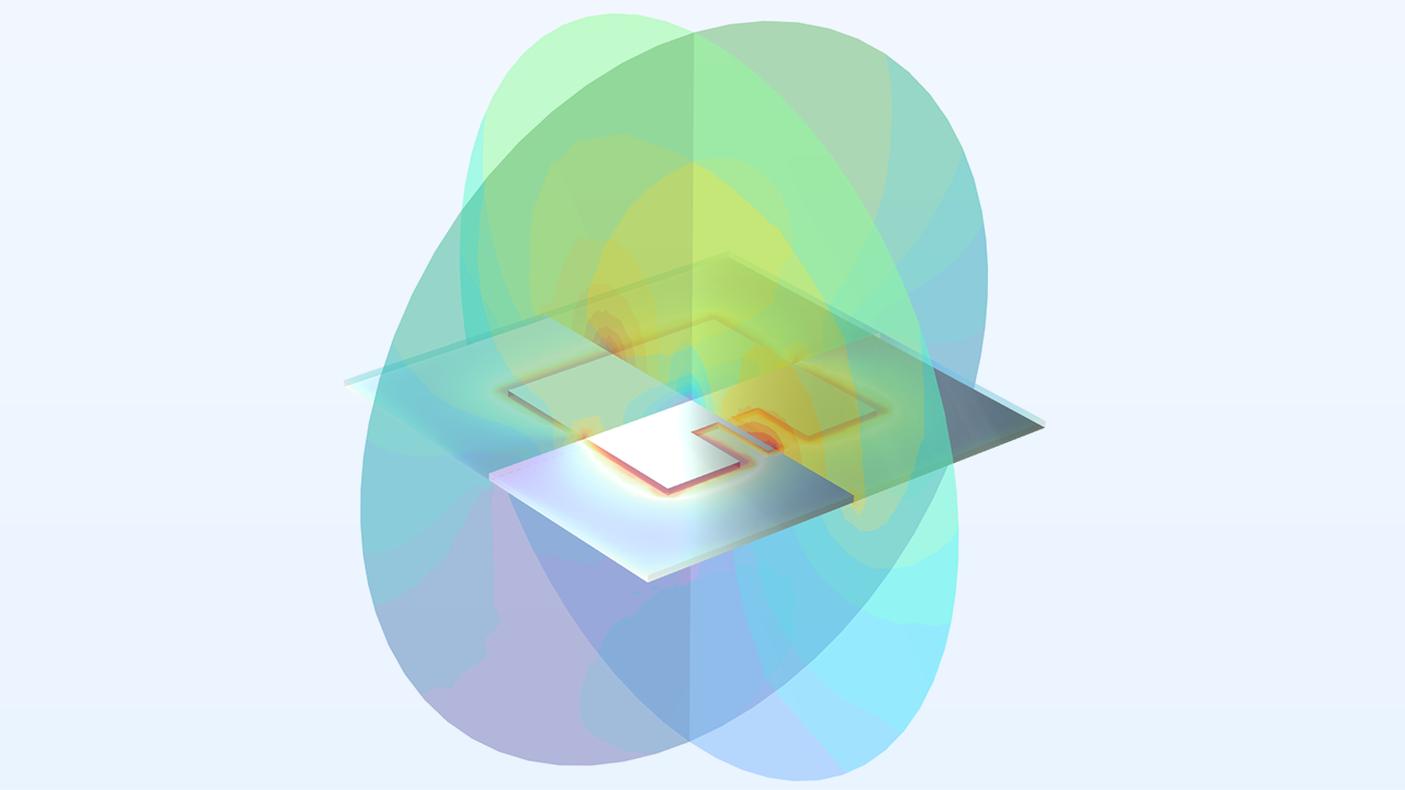
L'Application Library dell'RF Module è stata ampliata per introdurre la quantificazione dell'incertezza per i dispositivi a microonde, esaminando in che modo le variazioni dei parametri di input, come le proprietà dei materiali o le variazioni geometriche, influiscono sulle prestazioni del dispositivo in termini di parametri S. L'analisi comprende uno studio di screening per identificare i parametri che influenzano in modo più significativo le metriche di prestazione chiave. Inoltre, valuta gli effetti relativi di questi parametri e le loro interazioni nell'analisi di sensibilità. L'analisi di affidabilità valuta la robustezza del progetto finale rispetto alle variazioni dei parametri di progetto, determinando la probabilità di raggiungere i criteri di prestazione specificati. I tutorial Bow-Tie Antenna Optimization e Uncertainty Quantification Study for a Microstrip Patch Antenna illustrano questa nuova funzionalità.
Aggiunta della condizione al contorno all'interfaccia Electromagnetic Waves, Frequency Domain
La funzione Matched Boundary Condition è stata aggiunta all'interfaccia Electromagnetic Waves, Frequency Domain, rendendo i contorni trasparenti alle onde con una direzione di dispersione nota, riducendo al minimo le riflessioni. Per gli scenari con un campo incidente, è possibile utilizzare un sottonodo Reference Point per definire la fase dell'onda incidente.
Tutorial nuovi e aggiornati
La versione 6.3 di COMSOL Multiphysics® introduce diversi nuovi tutorial nell'RF Module.
Bow Tie Antenna Optimization*
Titolo in Application Library:
bow_tie_antenna_optimization
Download da Application Gallery
*Richiede l'Optimization Module
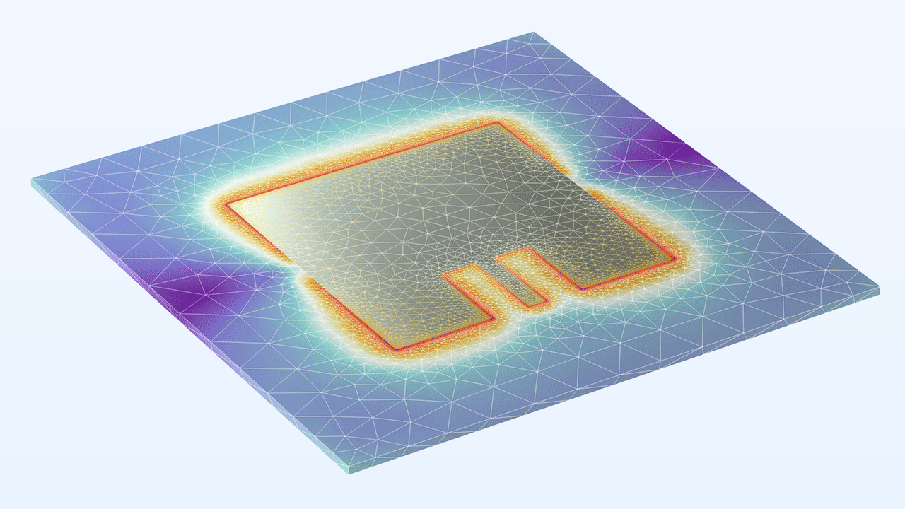
Mesh Adaptation Study for a Microstrip Patch Antenna
Titolo in Application Library:
microstrip_patch_antenna_mesh_adaptation
Uncertainty Quantification Study for a Microstrip Patch Antenna*
Titolo in Application Library:
microstrip_patch_antenna_uq
Download da Application Gallery
*Richiede l'Uncertainty Quantification Module
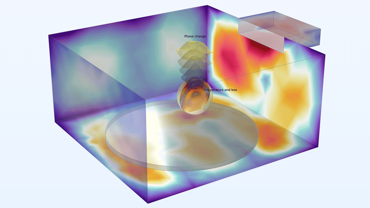
Rotating Microwave Oven with Phase Transition
Titolo in Application Library:
rotating_microwave_oven

