
When modeling a rotating machine, it’s important to study the vibrations influencing its behavior in order to avoid machine failure. One way to accomplish this is with the new Rotordynamics Module, an expansion to the add-on Structural Mechanics Module for the COMSOL Multiphysics® software. Today, we’ll introduce you to the Rotordynamics Module and walk you through its helpful features and functionality for improving your rotating machinery design process.
What Can You Achieve with Rotordynamics Modeling?
Let’s begin with a brief introduction to rotordynamics modeling. As we have mentioned previously on the blog, rotordynamics analysis helps enhance the functionality and safety of rotating machines, which are used across many industries, from aerospace technology to power generation.
For instance, say that you want to make sure that a generator, one type of rotating machine, avoids instabilities, damaging resonances, and failure caused by a poor design. You can use rotordynamics analysis to study the vibrations that both influence the physical behavior of the generator and are exacerbated by the generator’s rotation and structure.
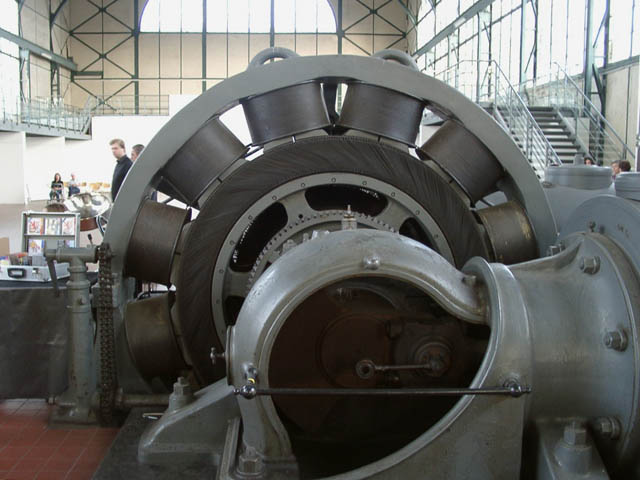
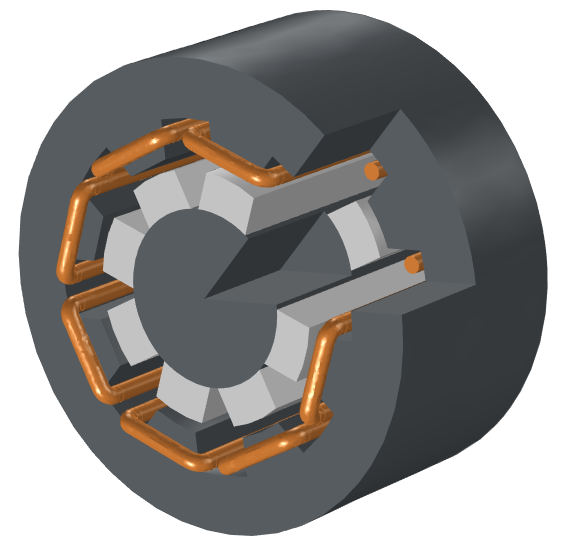
A generator (left) and a 3D model of a generator (right).
With simulation software, you can increase the accuracy and simplicity of your rotordynamics studies. And now, with the Rotordynamics Module, this process has become even more user friendly and flexible.
The Rotordynamics Module helps you set appropriate design parameters to keep responses within acceptable operating limits by analyzing resonances, stresses, strains, and the effects of lateral and torsional vibrations on rotating machinery. Additionally, you can use this module to take a closer look at how stationary and moving rotor components affect your design, as well as other parameters such as critical speeds, natural frequencies, and mode shapes. We’ll delve into a few specific benefits and features in the next section.
Why Should You Use the Rotordynamics Module?
One of the main benefits of the Rotordynamics Module is flexibility. With this module, you can easily customize your simulation analysis to study specific parts of a rotating assembly or the whole structure.
The latter of these options is achieved with the Solid Rotor interface in the Rotordynamics Module, which uses a 3D CAD geometry to represent the rotor and solid elements for finite element modeling. By studying all of the components in a rotating assembly, you can generate the most accurate results possible. While modeling the entire system is not necessary for stress and deformation of the rotor, it will increase the accuracy of the simulation. To obtain the distribution of the stress and deformation field in the whole domain, modeling the rotor as a solid element is necessary.
Using this interface, you can include nonlinear geometric effects, fully describe geometrical asymmetries, account for phenomena such as spin softening and stress stiffening, and more.
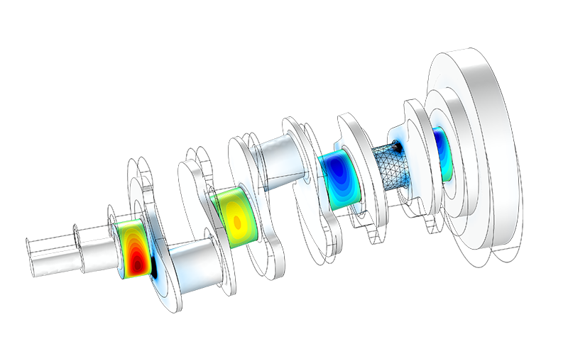
A crankshaft model that uses the Solid Rotor interface to analyze the bearings’ pressure distribution in the lubricant as well as the von Mises stresses.
What if you want your model to be less computationally expensive? You can turn to the Beam Rotor interface for a faster and more computationally efficient option for modeling rotating machines. In this interface, an edge along the rotor axis defines the rotor and the other rotating machine components are defined by creating points at their respective locations.
Investigating Foundations and Bearings in Rotating Machines
As another advantage, this module simplifies the modeling process for two key elements in a rotor system: foundations and bearings. First, let’s look at foundations, which are broken down into three different modeling options:
- Fixed foundations for a foundation that does not affect the rotor response significantly
- Moving foundations for a foundation and bearing that experience external vibrations
- Flexible foundations for a foundation that affects the rotor’s critical speed due to its flexibility
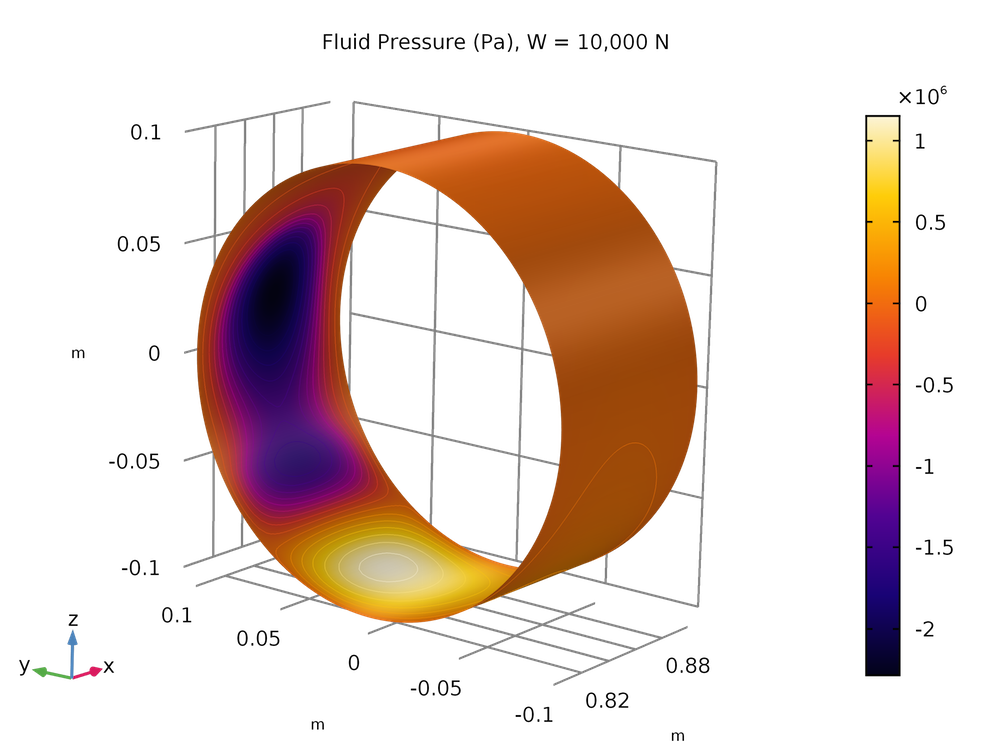
A model of the pressure in a hydrodynamic bearing.
Resting upon these foundations are bearings. Let’s first focus on journal bearings, which you can model in two ways with the Rotordynamics Module:
- By using lumped models with certain approximations
- By modeling a full hydrodynamic bearing, including a detailed analysis of the lubricant pressure and flow
This second option utilizes three different interfaces where the hydrodynamic part is based on a full Reynolds equation implementation. The Hydrodynamic Bearings interface models the behavior of journal bearings in detail and features an easy method for modeling an oil lubricant between a journal and bushing. The Solid Rotor with Hydrodynamic Bearing and Beam Rotor with Hydrodynamic Bearing interfaces both analyze a rotor, hydrodynamic bearing, and their interactions. However, as the names imply, the former uses solid elements to describe the rotor and the latter uses beams to define an approximated rotor.
If you’re interested in modeling thrust bearings, the Rotordynamics Module has you covered. This module includes three types of thrust bearings and behaviors: no clearance bearings, bearing stiffness and damping coefficients, and bearing forces and moments.
Choose from a Range of Study and Plot Types
Using the previously discussed features and functionality, you can design a model that fits your specific needs. However, there is even more customization available in the Rotordynamics Module, which offers a variety of study types.
With the included study types, you can easily model gyroscopic effects. Vibrational effects, meanwhile, are modeled from the perspective of a corotating observer. To achieve this, we use a coordinate system that rotates along with the rotor. This removes the need to physically rotate the rotor to simulate the assembly, simplifying the modeling process. Modeling in corotating frame also allows an eigenfrequency analysis of a rotating system, which would otherwise be impossible due to the nonlinearity of the rotation when the system is observed in a space-fixed frame.
The available study types apply to static and dynamic analyses and include:
- Stationary study
- Eigenfrequency study
- Frequency and time-domain study
- Transient with FFT study
Note that for rotordynamics analyses, the definition of a stationary study differs from conventional analyses.
After you’ve run your study, it’s time to format your results and share them with other people. Doing so requires choosing the plot type that best visualizes your particular results. Take a look at the four images below to see a few of the available plot types that you can create based on your rotordynamics analyses.
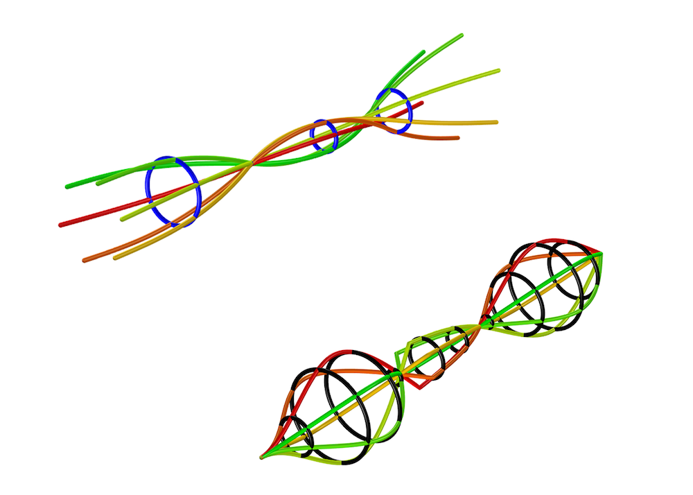
Whirl plots plot a rotor’s mode shapes around its axis.
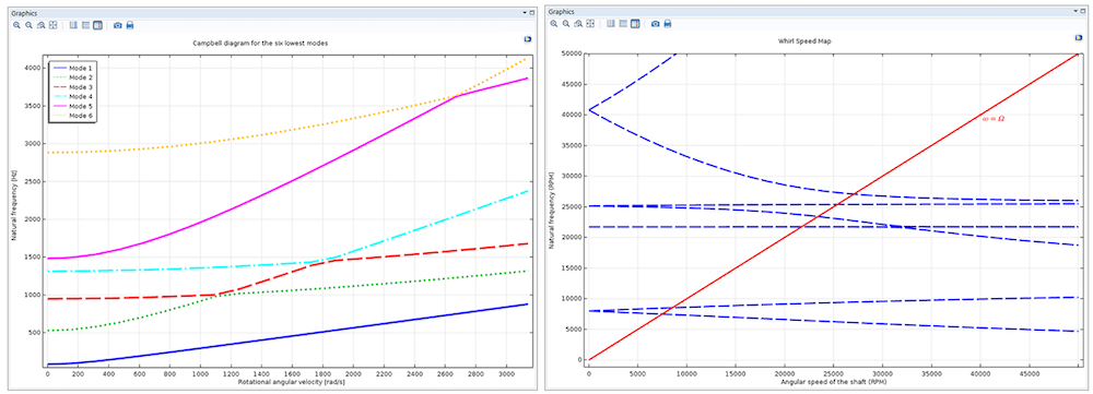
Campbell plots plot the variations of a rotor’s natural frequency variations in relation to its speed.
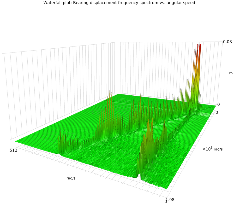
Waterfall plots plot frequency spectrum variations when the rotor’s angular speed increases.
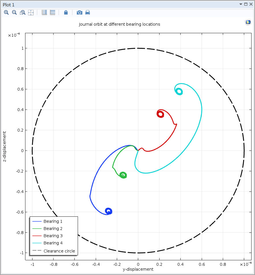
Orbit plots plot rotor displacements at certain points, including the locations of bearings and disks.
To learn more about the Rotordynamics Module, click on the button below. You can also contact us with any questions you may have. Happy modeling!
Further Resources on Rotordynamics Analysis
- Read more about modeling rotating machines on the COMSOL Blog:



Comments (3)
Shuai Zhu
July 25, 2017Hi, Caty Fairclough
I encounter a problem, when I use COMSOL for rotor dynamics.
The problem can be expressed as follows:
A group gives the steps for matrix extract of ANSYS, see http://structdynviblab.mcgill.ca/pdf/AnsysMatlab.pdf.
I want to know whether COMSOL can export the ralated matrix for the future computation.
Best, Hamilton
Shuai Zhu
July 25, 2017Hi, Caty Fairclough
I encounter a problem, when I use COMSOL for rotor dynamics.
The problem can be expressed as follows:
A group gives the steps for matrix extract of ANSYS, see http://structdynviblab.mcgill.ca/pdf/AnsysMatlab.pdf.
I want to know whether COMSOL can export the ralated matrix for the future computation.
If so, can I have the tutorial for that ?
Thanks!
Best, Hamilton
Prashant
July 26, 2017 COMSOL EmployeeHi Shuai,
Short answer to your question is, yes you can extract the mass, damping and stiffness matrices and many other matrices in COMSOL. For the detailed answer, we suggest that you forward your question to support@comsol.com.
Thanks,
Prashant