Of the 72 million potential hearing aid users around the world, each needs a device fitted to meet their needs. In-the-ear measurements are performed to ensure both comfort and effectiveness. These measurements require the use of a microphone — the size of which can cause issues. The device can be too large to fit into the measured sound field. Alternatively, it can be too big compared to the wavelength and disturb the acoustic field. One solution is a probe tube…
The Ins and Outs of Probe Tube Microphones
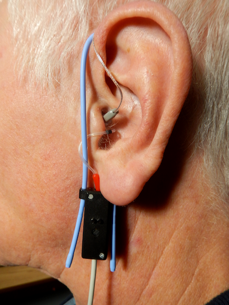
Probe tubes are attached to microphone cases in order to distance the device from the sound field being measured. When fitting hearing aids, the tube is inserted into the ear canal with the microphone worn on the outside of the ear. This system provides measurements that calibrate and verify the comfort and effectiveness of hearing aids, specifically if the device amplifies signals to the level that the patient needs. In fact, the American Speech-Language-Hearing Association and the American Academy of Audiology say that in-the-ear measurements are the preferred method for verifying hearing aid performance.

A probe tube microphone performing in-the-ear measurements. Image by Cstokesrees — Own work. Licensed under CC BY-SA 3.0, via Wikimedia Commons.
When adding a probe tube to a microphone, we have to consider how these two components interact with one another. For instance, we need to understand how the probe affects the sensitivity of the microphone, thus the measurements that the device delivers. As we show here, multiphysics simulation provides answers.
Analyzing the Sensitivity of a Probe Tube Microphone Design
For this example, we use a time-dependent model that consists of a generic probe tube microphone configuration. It includes:
- External acoustic domain
- Probe tube
- Cavity before the microphone diaphragm
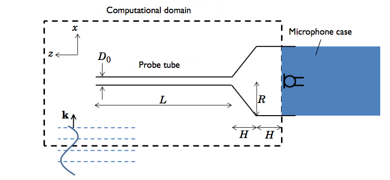
The probe tube is made of an elastic material with a Young’s modulus of 0.1 and a Poisson’s ratio of 0.4. In the schematic below, L represents the length of the tube, while D0 is its outer diameter. The cavity in front of the microphone is a cylinder with a radius of R and height of H. This cavity is connected to a cone that has a bottom radius of R and top radius of D0. An external sound field with the wave vector k hits the probe tube. Note that this sinusoidal wave moves in the positive x direction and has an amplitude of 1 Pa.

The probe tube microphone configuration.
To model this probe tube microphone design, we use the Pipe Acoustics, Transient interface. In our analysis, the probe tube is treated as a 1D structure — a valid assumption as long as we neglect the interaction between this component and the incoming sound field. We also assume that no significant thermal and viscous boundary losses occur inside the tube. This holds for the current configuration in which the incident field is a monochromatic wave. Since the diaphragm is not a fully rigid structure, we assume a resistive loss that is consistent with the impedance of common condenser microphones. This gives us a fully coupled acoustics simulation, as the probe tube is connected to two separate 3D pressure acoustics domains.
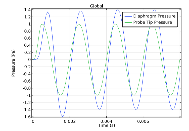
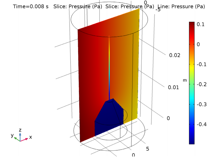
When analyzing a probe tube microphone, an important parameter to consider is the relationship between the pressure at the tip of the probe and the pressure at the diaphragm. This is a necessary step for calibrating the measurement system. The plot below on the left shows that the solution, following an initial transient, becomes periodic after around 4 ms. The system then experiences a gain of about 1.4 and a phase shift takes place. These two factors are dependent on the frequency of the applied signal, which is a pure harmonic tone of 500 Hz. The plot on the right depicts the pressure distribution in the xz-plane at the end of the time interval.
Left: Diaphragm pressure vs. probe tip pressure. Right: Pressure distribution in the xz-plane at 8 ms.
These results show the potential of using the COMSOL Multiphysics® software to analyze probe tube microphone designs. With a better understanding of how the probe tube and microphone interact, it is possible to further improve the design of these systems for fitting hearing aids and for other applications.
Find More Examples of Modeling Microphones with COMSOL Multiphysics®
- Browse other microphone modeling tutorials in the Application Gallery:
- Read this related blog post:


Comments (0)