
One useful — but in my experience, rarely used — capability available within COMSOL Multiphysics is the ability to compute design sensitivities. Assuming that you have a single objective function that is computed based on your finite element model, you can easily compute how sensitive this objective function is with respect to any model input, using only the core COMSOL Multiphysics package. In this blog post, we will look at how to use this functionality.
An Introductory Example: The Parallel Plate Capacitor
Let’s start this conversation with a very simple problem — computing the capacitance of two parallel flat square metal plates, of side length L=1\:m, separated by a distance D=0.1\:m, and with a dielectric material of relative permittivity \epsilon_r= 2 sandwiched in between. Under the assumption that the fringing fields are insignificant (a rather severe assumption, but we will use it here to get started), we can write an analytic expression for the capacitance:
where \epsilon_0 is the permittivity of free space.
We can easily differentiate this expression with respect to our three inputs to find the design sensitivities:
Now let’s look at computing these same sensitivities using the functionality of COMSOL Multiphysics.
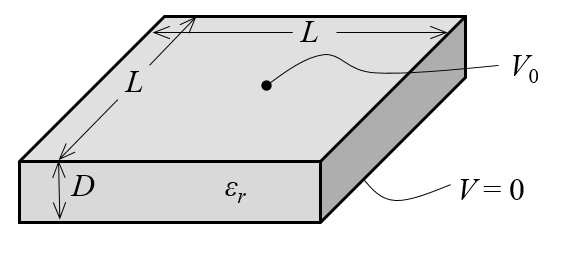
Schematic of a parallel plate capacitor model, neglecting the fringing fields.
We can start by building a model using the Electrostatics physics interface. Our domain will be a block of length L and height D with a relative permittivity of \epsilon_r. The boundary condition at the bottom is a Ground condition, and at the top, an Electric Potential condition sets the voltage to V_0=1\:V. The sides of the block have the default Zero Charge boundary condition, which is equivalent to neglecting the fringing fields. We can solve this model and find the voltage field between the two plates. Based on this solution, we can also calculate the system capacitance based on the integral of the electric energy density, W_e, throughout the entire model:
This equation does assume that one plate (or terminal) is held at a voltage V_0, while all other terminals in the model are grounded. The integral of the electric energy density over all domains is already computed via the built-in variable comp1.es.intWe, and we can use it to define an expression for the computed capacitance. Of course, we will want to compare this value and our computed sensitivities to the analytic values so we can define some variables for these quantities. We can use the built-in differentiation operator, d(f(x),x), to evaluate the exact sensitivities, as shown in the screenshot below.
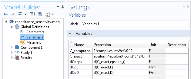
Variables are used to compute the model capacitance, as well as to compute the exact capacitance and its sensitivities. The built-in differentiation operator, for example d(C_exact,L), can be used to evaluate the exact sensitivities.
After solving our model, we can evaluate the computed system capacitance, compare it to the analytic value, and evaluate the design sensitivities analytically. Now let’s look at how to compute these sensitivities with COMSOL Multiphysics.
The parameters that we are considering affect both the material properties as well as the geometric dimensions of the model. When the design parameters affect the geometry, we need to use the Deformed Geometry interface, which lets us evaluate the sensitivities with respect to a geometric deformation.
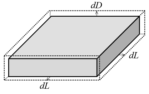
The design parameters will affect a change in the geometry as shown. The hidden faces experience no displacement normal to the boundaries.
We introduce two new Global Parameters, dL and dD, which represent a change in L and D. These will be used in the Deformed Geometry interface, which has four relevant features. First, a Free Deformation feature is applied to the domain, which means that the computational domain can deform based on the applied boundary conditions. Next, Prescribed Mesh Displacement features are applied to the six faces of the domain. In the screenshot below, the deformation (dL) normal to the faces is prescribed as shown in the sketch above.
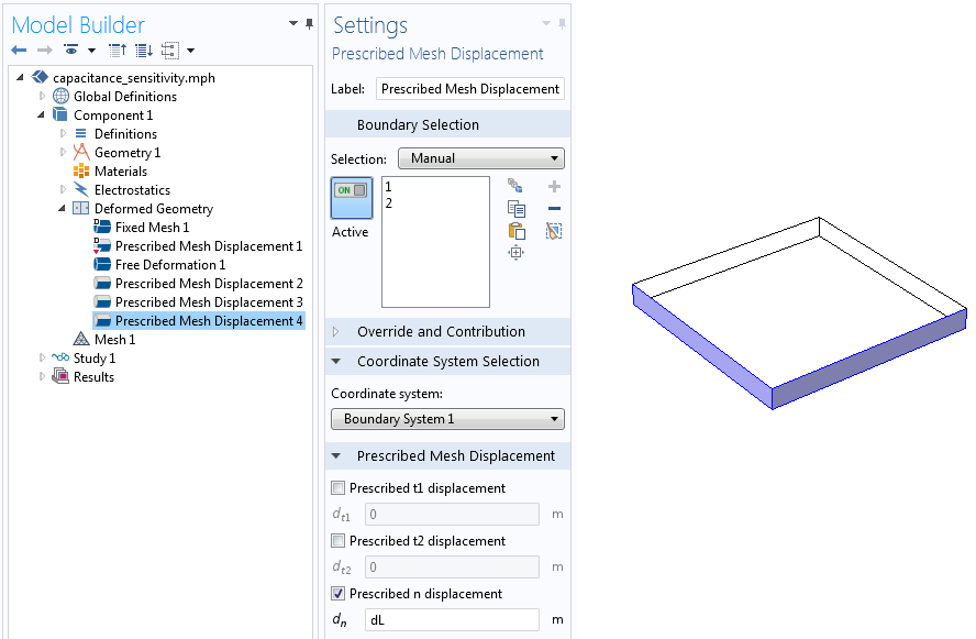
The Prescribed Mesh Displacement features are used to control the displacement normal to all domain boundaries.
Finally, to actually compute the sensitivities, we must add a Sensitivity node to the Study Sequence, which is available when the Advanced Study Options are enabled. This is shown in the screenshot below. You will want to enter the objective function expression, in this case C_computed, as well as all of the design parameters that you are interested in studying. Also, choose the value for the design parameters around which you want to evaluate the sensitivities. Since dL and dD represent an incremental change in the dimensions, we can leave these both at zero to compute the sensitivities for L=1\:m and D=0.1\:m. The parameter controlling the material permittivity needs no special handling, other than to choose it as one of the parameters in the Sensitivity study.
There are two options in the form shown below for the gradient method:
- The adjoint method is fast and solution time will not depend on the number of parameters studied. In fact, the adjoint method adds only the equivalent of a single Newton iteration to the total computational cost.
- The forward method solution time increases with the number of parameters, but does additionally return the sensitivity of the entire solution field, which may be useful in some cases.
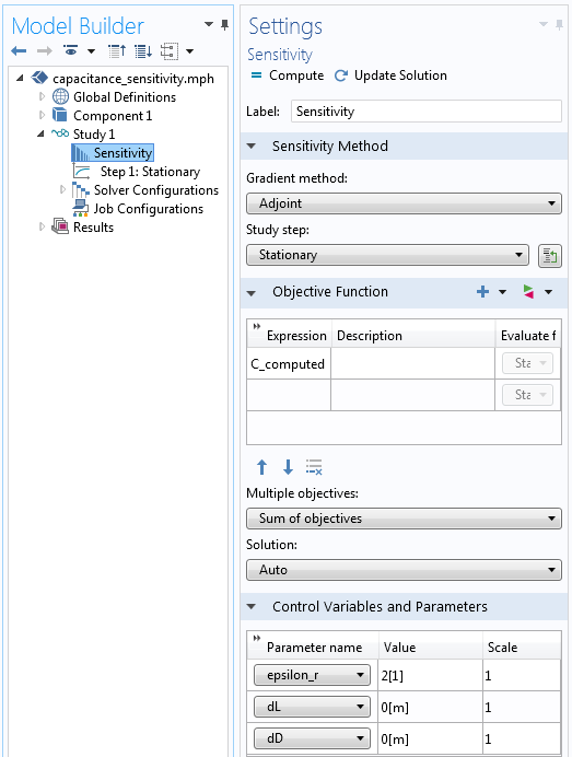
A Sensitivity feature using the adjoint method is added to the study sequence, and the settings show the objective function and the parameters that are considered.
After solving, you will now be able to go to Results > Derived Values > Global Evaluation and enter the expressions fsens(dL), fsens(dD), and fsens(epsilon_r) to evaluate the sensitivity of the capacitance with respect to the design parameters. Of course, you can also compare these to the previously computed analytic sensitivities and observe agreement.
| Analytic | Computed | |
|---|---|---|
|
\frac{\partial C}{\partial \epsilon_r}
|
88.542 nF | 88.542 nF |
|
\frac{\partial C}{\partial L}
|
354.17 nF/m | 354.17 nF/m |
|
\frac{\partial C}{\partial D}
|
-1770.8 nF/m | -1770.8 nF/m |
Now that we have the basic idea down in terms of computing the sensitivity of the capacitance of this system, what else can we do? Certainly, we can move on to some more complicated geometries, but there are a few points that we need to keep in mind as we move beyond this example.
Limitations and Scope While Computing Design Sensitivities
There are two conditions that must be fulfilled for sensitivity analysis to work. First, the objective function itself must be differentiable with respect to the solution field. This means that objective functions such as the maximum and minimum of a field are not possible. Second, the parameters must be continuous in the real-number space. Thus, integer parameters (e.g., the number of spokes on a wheel) are not possible.
Sensitivity calculations are not currently available for eigenvalue problems, nor ray tracing or particle tracing.
The design parameters themselves are typically Global Parameters, but you can also use the Sensitivity interface to add a Control Variable Field defined over domains, boundaries, edges, and points as desired.
Objective functions are typically defined in terms of integrals of the solution over domains or boundaries. It is also possible to set up an objective function as a Probe at a particular location in the model space. Any derived quantity based on the solution field, such as the spatial gradients of the solution, can be used as part of the objective function.
Closing Remarks
Computing design sensitivities is helpful for determining which parameters affect our objective function the most and gives us an idea about which parameters we might want to focus on as we start to consider design changes. Some other examples that use this functionality include our tutorial model of an axial magnetic bearing and our sensitivity analysis of a communication mast detail. Of course, this method can be used in far more cases than we can describe at once.
This story continues when we start to use these sensitivities to improve our objective function — where we optimize the design. This can be done with the Optimization Module, which we will cover in an upcoming blog post.


Comments (21)
Ivar Kjelberg
August 6, 2015Hi Walter
Thanks again for a nice and clear example, the Blog pages are really helpful and replaces well the long time missing Tips&Tricks of the old v3 COMSOL News.
What I could not yet from your short description is if you are, with ES, calculating the capacitance including the fringe field effects around the capacitor plates.
The perfect match you get show clearly that Sensitivity calculations works perfectly when we apply pure geometrical differential equations, as expected.
But, how well does the simplified geometrical model match when one include the electric field contribution around the capacitor plate ? This is when FEM is/should be closer to the “reality” than simplified geometrical calculations.
Sincerely
Ivar
Walter Frei
August 6, 2015 COMSOL EmployeeDear Ivar,
Thank you for your comments.
Just in case it was not completely clear: COMSOL uses the finite element method and the adjoint method to compute these sensitivities, so there are no “pure geometrical differential equations” being used in this, or any other, example.
I simply chose an example which could be compared to an easily derivable analytic solution. The finite element basis functions used here are applicable for *any* geometry, but of course I leave it to our dear readers to verify this.
Best,
Malkhaz Meladze
August 6, 2015Dear Walter,
I agree with Ivar, the Comsol Blogs are always helpful and examples are always chosen thoughtfully.
This blog is not an exception – I learned much from it. Thank you.
I repeated the example in different variations and get the same numbers as displayed in the table above only if I specify “Prescribed Mesh Displacement(s)” as dL/2 and dD/2. I am wondering what I am doing wrong. And apparently I am doing something wrong, because whatever variation I run, in each case I get the same warning: “New constraint force nodes detected: These are not stored.”
Best regards,
Malkhaz
Walter Frei
August 7, 2015 COMSOL EmployeeDear Malkhaz,
Yes, there will be a warning when you run this model, but you can ignore it. The sensitivity results themselves are valid.
With respect to your results: it sounds like you are applying the deformation on both sides of the domain. You can also set up one side to have a displacement of zero, and the other to have a displacement of dL and dD. That way, you avoid the divide by two.
Best,
Alexey Trukhin
September 12, 2015Dear Walter,
Thank you very much for the blog.
Could you please elaborate on why a sensitivity analysis cannot be done with a ray optics module?
Kind regards,
Walter Frei
September 22, 2015 COMSOL EmployeeDear Alexey,
The Ray Optics Module uses a ray tracing approach (solving ODE’s for the rays) rather than using the finite element approach (solving PDE’s for the fields) and the adjoint sensitivity calculation in COMSOL only works with problems solved via the finite element method. (Of course, in the future we may introduce yet more methods.)
Alexey Trukhin
September 24, 2015Dear Walter,
If I undestand you correctly, there is no any tools for a sensitivity analysis in the Ray Optics module in the current version of COMSOL (version 5.1)?
Walter Frei
September 24, 2015 COMSOL EmployeeDear Alexey,
It would be more fair to say that the adjoint sensitivity calculation which is described here is only available for finite element based problems. The Ray Optics Module is built upon different technology. You can, of course, use the Parametric Sweep functionality to observe the variation of an objective function with respect to design parameter changes.
Alexey Trukhin
September 26, 2015Dear Walter,
Thank you very much for clarifying the situation. The sensitivity analysis is much needed in opto-mechanical field due to the fact that the most optical devices (say optical sights and binoculars) have to be adjusted (adjusting mirrors or prism, for example). That is why it is preferable to have a sensitivity analysis in the Ray Optics module.
However, I have not found any restriction on using the Optimization module in the Ray Optics module in the documentation. But, assuming that both Sensitivity and Optimization modules are allied to some extent, can we declare that the Optimization module cannot be utilized in the Ray Optics module either taking into consideration that the Optimization module uses PDE`s for solving optimization problems?
Walter Frei
September 28, 2015 COMSOL EmployeeDear Alexey,
You can use the Optimization Module with the Ray Optics Module, you would simply have to use the numerical derivative approach, rather than the analytic derivative approach developed here. If you do have detailed questions about this, and are considering the Optimization Module for your modeling needs, we encourage you to contact your Support Staff, as this conversation on the Ray Optics Module is getting a bit beyond the scope of this blog.
Andrey Ivanov
March 10, 2017Why you didn’t write, that to add a Sensitivity node to Study, you must first enable advanced study options, which are not enabled by default? Spent so much time before found how to add that node…
Bridget Cunningham
March 10, 2017 COMSOL EmployeeHi Andrey,
Thank you for making note of this. The post has been updated to include mention of enabling the Advanced Study Options.
Best,
Bridget
Nicolò Riva
November 20, 2018Dear Dr. Frei
Thanks for your work and interesting blog, as usual.
I have a couple of quick questions:
– Is it possible to use it in a Time Dependent-Study?
– This question it is more philosophical…Why use the Deformed Geometry instead of a normal Sweep Parameters with the parametric geometry? Is there any particular reason? Is there any mathematical reason?
Thank you for your help and availability!
Best
Nicolò Riva
Walter Frei
November 20, 2018 COMSOL EmployeeDear Nicolò,
Yes, it is possible to do this with a time-dependent study, but the sensitivity will be computed with respect to the objective value at the last time step. (Which you can make an integral over time, e.g.: https://www.comsol.com/support/knowledgebase/913/) Also, be aware that your governing equation must have a time-derivative, it cannot be quasi-static.
With respect to your second question: The Deformed Geometry is the mechanism by which the software computes these sensitivities. If you use geometric parametrization, this functionality is not available.
Best Regards,
Nicolò Riva
November 21, 2018Dear Walter,
Thanks for the very quick reply! I will try with the time dependent study and then I will come back to you in case.
Best
Nicolò Riva
November 26, 2018Dear Walter,
I tried to implement as you said the sensitivity node with a time-dependent study.
Unfortunately it does not work and when I tried to calculate the sensitivity I get
No stored functional sensitivity data.
Failed to evaluate expression.
– Expression: fsens(dAgY)
Failed to evaluate variable.
– Variable: fsens_dAgY
– Defined as: fsens(dAgY)
Failed to evaluate expression.
– Expression: fsens_dAgY
It is like if in the sensitivity study it is not considered the time dependent option. In fact, when I select the menu “Study steps” in the settings (just above the time dependent study), I can not select any study and there is written “None” instead of Time-dependent …
Is it clear what is the issue? I think that he can not evaluate the variable because I can not perform the study…
I defined in the main variables an integral such as
obj=timeint(1,14,Current)
and then I put obj in the objective functions.
In any case, I can’t obtain such information…
Thanks for any reply and for your help
Best
Nicolò
Kamuran Turksoy
April 20, 2020Hi Nicolò,
Could you figure out a way to fix this problem? I am having exactly the same problem.
Walter Frei
November 26, 2018 COMSOL EmployeeDear Nicolò,
As your questions are touching upon your own implementation, rather than functionality in general, you will want to contact your COMSOL Support Team: support@comsol.com
Note also, as described in KB913, (https://www.comsol.com/support/knowledgebase/913/) timeint is for results evaluation only.
Tammy
February 19, 2019Hi, I am recently using Comsol multiphisycs 5.1. I created a model for the study of a parallel plate capacitor with mica dielectric. Now to test the sensitivity of the design I would like to change the value of the permittivity in a range between 0.5 and 70 and calculate the capacity. Could someone direct me on the steps to be taken? thank you
Ramesh Ramanaiah
March 24, 2021Hi sir,
Thank you so much for the information and useful blog. So am using this idea to find the sensitivity for my model (electrical capacitance tomography). which has 8 electrode attached peripherally. As in the variable if i give the expression it is not coming it shows in red in colour which is not accepting. I am new for this comsol world but trying to learn and do for my thesis work. So what will be the reason?
Thanks,
Mervenaz Sahin
April 8, 2021Hello Walter. To get the adjoint output, should I add Sensitivity study in a topology optimization model?
Also, is there any easy way to get the sensitivity values of the elements, not the nodes.
Thank you so much,