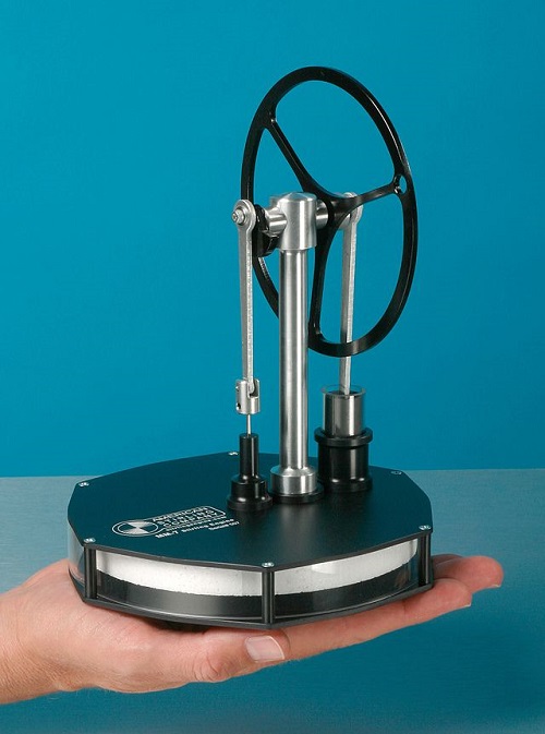
Stirling engines, or heat pumps, are systems that are able to work on incredibly low temperature differences. In fact, some types of Stirling engines only need human body heat in order to operate. Here, we explore the dynamics of this interesting machine that you can build at home and demonstrate how to model it using COMSOL Multiphysics.
Modern Applications for a Rather Old Idea
Let’s begin by taking a step back in the history of the Stirling engine. Denominated the “engine of the future,” the Stirling engine was first developed by Robert Stirling nearly 200 years ago in 1816. While the technology never really came out on top, this type of heat engine has found extensive use in many modern applications. For example, the solar Stirling engine is used to directly transform solar heat into mechanical energy, which is in turn applied to powering a generator and producing electrical power. Additionally, analogous approaches exist that are based on geothermal energy or use industrial waste heat. The most astonishing modern application of the Stirling engine may be its operation in Swedish submarines — the absence of air is not an issue for a Stirling’s propulsion.
From Thermal Energy to Mechanical Work
We’ve touched upon some of the applications of Stirling engines, but how does this machine operate? In a Stirling engine, thermal heat is converted into mechanical work (or the other way around) in a cyclic process. This can be realized in different ways, but the principle remains the same: The engine cycles through the four processes of cooling, compression, heating, and expansion. A gas is used to transport the heat from a permanent hot side to a cold side. The efficiency of the engine is restricted by the efficiency of the Carnot cycle.
In contrast to conventional engines, Stirling engines do not need to reach high temperatures to operate. Some Stirling engines only need a small Kelvin temperature difference between the hot side and the cold side. Furthermore, the sound level and subsequent energy losses are very low because there are no explosions and no exhaust. However, Stirling engines are most suitable for applications where constant power is required, as controlling dynamic power regulation would be an extensive task. This is likely the most prominent reason as to why there are still no cars powered by Stirling engines.

A Stirling engine operates using the heat from a human hand. (“A Stirling engine that works solely with the energy taken from the temperature-difference from the surrounding air and the palm of the hand” by Arsdell — Own work. Licensed under Creative Commons Attribution-Share Alike 3.0 via Wikimedia Commons).
Building Your Own Stirling Engine
For those of you with some experience in handcrafting, it is possible to build your own Stirling engine at home, without the need for professional tools or experience. Several video tutorials are available on YouTube that include instructions designed to guide you through the building process. The easiest of these examples is probably the version consisting of a cola can and some domestic odds and ends.
While easy to build, this model of a Stirling engine is likely not optimized from an efficiency point of view. Creating a numerical model of the engine offers a better solution.
Modeling a Stirling Heat Pump with COMSOL Multiphysics
With a numerical model of a Stirling engine, we are able to find and test sets of materials as well as parameter adjustments. The involved physics are heat transfer and fluid flow, and the mechanical process can be simplified by solving the equation of motion as an additional ODE.
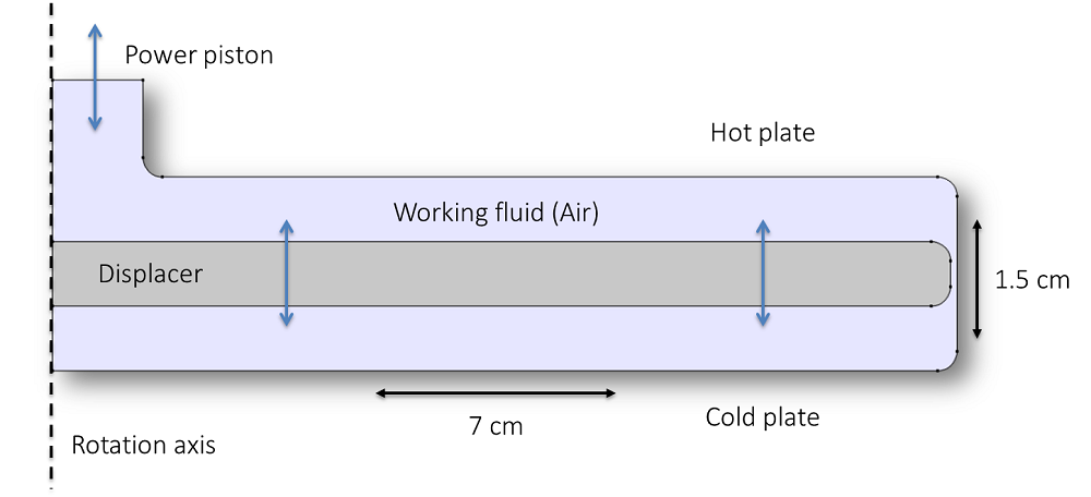
The 2D-axisymmetric model consists of a main cylinder that includes the working fluid (air) and the displacer. The small cylinder on top contains the power piston. Both the displacer and the power piston are connected in parallel and joined 90º out of phase on a crankshaft, which is not featured as part of the model. The whole setup corresponds to a gamma type Stirling engine.

A model of a Stirling heat pump.
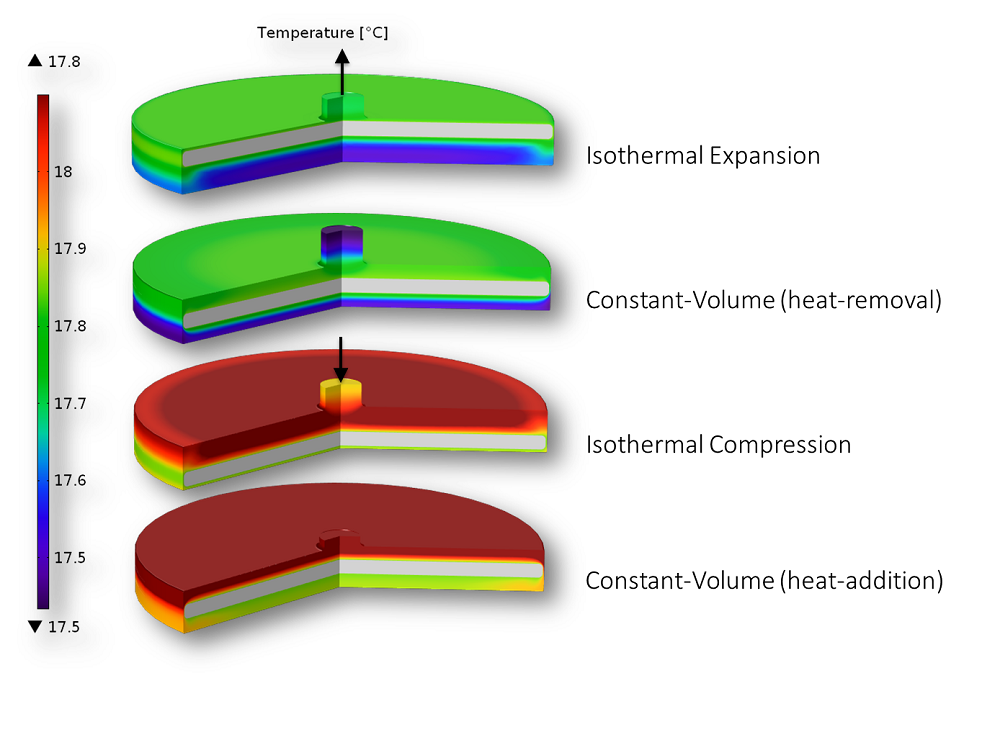
Here, the heat transport within the working gas is solved. The mechanical part is realized via a moving mesh (ALE) approach: The displacer and the power piston are free to move in the z-direction. The displacement is prescribed here, corresponding to a heat pump. Mechanical work is used to move thermal energy opposite to the direction of spontaneous heat flow. The other way around — a Stirling engine — can also be modeled by applying a heat source and solving for the resulting pressure forces at the power piston and the displacer. In any case, the system runs through a certain chain of processes that can be divided into the four steps of the Carnot cycle:

Thermodynamic processes that are acting on the working fluid.
While its efficiency is nowhere near the theoretical Carnot cycle diagram, the resulting pressure/volume graph shown below does correspond to experimental results.

A pressure/volume graph of the Stirling cycle.
The real advantage of the model is that we can analyze the physics within the heat pump. For example, the animation below indicates velocity distribution during the operation of the heat pump.
Velocity distribution during the heat pump’s operation.
Since the piston brings mechanical energy needed to pump heat, we can also investigate the dynamic temperature distribution within the heat pump during operation.
An animation depicting temperature distribution.
Improving Efficiency
If you are looking to improve the efficiency of the Stirling engine, the goal is to maximize the enclosed area in the pressure/volume graph. This area corresponds to the work that is done by the engine. The engine’s overall efficiency can be improved in multiple ways. If we choose a working gas that features a high specific gas constant (i.e., a low molar mass), this will maximize the isothermal expansion (and therefore the work ability) of the engine. This is why hydrogen and helium are preferred as working gases. Another possibility is to maximize the heat that is transported by the displacer through using a porous medium as a regenerating displacer (see this paper).


Comments (3)
Siddharth Ramachandran
January 25, 2019Can I get a tutorial for this simulation? I have done the geometry but finding trouble in giving moving mesh/ALE approach…
Phillip
January 28, 2019 COMSOL EmployeeSorry, but there is no tutorial for this simulation. Please contact the COMSOL support team for assistance.
mr v
July 23, 2021Can I request this simulation file? It will help me a lot and I will be very grateful