
As a technical support engineer, one of the most common technical questions I receive is: “How can I compute the mass conservation of a fluid flow simulation or the energy balance of a conjugate heat transfer simulation?” This is often requested to investigate and ensure a simulation’s accuracy. Here, I will demonstrate how to perform these calculations in the COMSOL Multiphysics® software and introduce some predefined variables available for postprocessing the energy rate terms of the energy balance equation.
Let’s Start with Mass Conservation
To demonstrate the different topics covered in this blog post, I’ll use the example of an aluminum heat sink, which is often used to cool off electrical devices by dissipating heat. This tutorial model is available in its steady-state version in the COMSOL Multiphysics Application Library if you have the Heat Transfer Module or CFD Module.
The heat sink is made of aluminum, shaped with a cluster of pillars for cooling, and mounted on a chip that is made of a silica glass material. In the model setup, the heat sink sits inside of a rectangular channel with an inlet and outlet for airflow. The chip acts as a heat source and generates 1 watt.
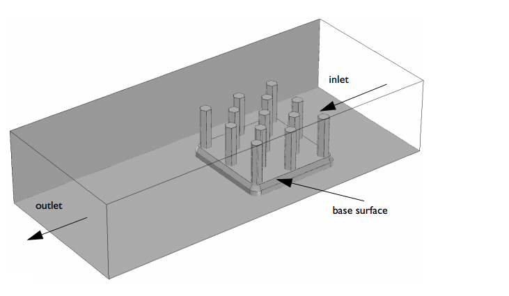
The geometry of a basic heat sink.
In fluid dynamics, mass conservation leads to a well-known local continuity equation:
By integrating this equation over the fluid domain and applying the divergence theorem, we obtain the global formulation of the mass conservation.
Therefore,
Let’s take a more specific look at the equation above. Whenever you are modeling a fluid flow simulation, you can evaluate this equation in order to check the mass conservation accuracy of your model. In any steady-state analysis, this equation reduces to \int_{\partial\Omega} \rho{\bf{u}} \cdot {\bf{n}} \ dS = 0 and states that the rate at which mass enters a system is equal to the rate at which mass leaves the system. In other words, the mass flow at inlets and outlets must balance.
A common mistake is to assume that mass conservation reduces to the volumetric flow rate conservation \int_{\partial\Omega} {\bf{u}}\cdot {\bf{n}} \ dS = 0. If the fluid density is constant, as for incompressible flow, the continuity equation simplifies to \nabla \cdot {\bf{u}} = 0, which states that the divergence of the flow velocity vanishes. In the case of incompressible flow, the assumption is then right. However, in most engineering problems, this assumption cannot be considered. Roughly speaking, in the case of motionless boundaries, we can consider it as long as the density does not depend on any variable (such as absolute pressure, temperature, concentration, etc.) that can lead to a change in density along the streamlines.
That said, let’s check the mass conservation accuracy of a fluid flow simulation within COMSOL Multiphysics. For this purpose, we can use the Derived Values feature — a useful postprocessing feature for calculating integrated quantities for each solution in a data set. To create a derived integration value, we go to Results > Derived Values > Integration > Surface Integration or Volume Integration. Then, we select the boundaries or volumes on which the integral should be carried out. Finally, we type the expression to be integrated.
The Derived Values feature generates a table with numerical values; you cannot perform mathematical operations with the different values. So, if you, for example, want to subtract one from the other or compute ratio, it is also handy to define integration operators in the Definitions > Component Couplings. This way, these operators become available for mathematical expressions and can be freely used in the variables definition in the Variables list. Once this is done, you can present them in the Derived Values list.
Here, the expression for both inlet and outlet mass flow rates is written as spf.rho*(u*nx+v*ny+w*nz), as shown in the figure below. spf.rho denotes the variable used to define the density of the fluid; (u,v,w) is the velocity field vector; and (nx,ny,nz) is the normal vector at the selected boundaries automatically computed by COMSOL Multiphysics. The rate of density change can be expressed as d(spf.rho,t). The d operator is intended to perform a derivation of a variable with respect to another variable. Here, we take the time derivative of the fluid density.
Step calculation for each mass flow rate term from the mass conservation equation.
In the static case of the heat sink simulation, the mass flow rates at the inlet and outlet boundaries are depicted below. The relative mass difference between the inlet and outlet is around 1e-5, which is less than the relative tolerance setting for the solver, which is set to 0.001. The mass conservation is therefore pretty accurate.

Mass balance results for a stationary study.
We can also perform a time-dependent analysis of the same model. The total time of the simulation is set to be 20 minutes and the base of the heat sink experiences 1 watt of heat flux during the entire simulation time. The relative tolerance of the solver is set to 0.001. The results of this simulation can be seen in the following animation. We set the simulation time to be long enough to reach both the thermal and fluid flow steady state.
The fluid flow streamlines are colored with the velocity norm and the temperature is plotted on the boundaries.
The mass balance results for the transient analysis are given in the following figure.
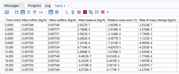
Mass balance results for a time-dependent study.
The accuracy is still good.
Calculating the Energy Balance
From the first law of thermodynamics and mechanical laws, the well-known global heat balance equation can be derived.
Here, Q_\mathrm{{exchange}} refers to the exchanged heat rate, taking into account conductive heat flux, -k\nabla T; radiative heat flux, {\bf{q}}_\mathrm{{rad}}; and additional heat sources, Q; such as electromagnetic heat sources (Joule heating), induction heating, or any user-defined heat source. P_\mathrm{{stress}} represents the stress power induced by mechanical stresses and E_\mathrm{{system}}=\int_\Omega E \ dm is the internal energy.
The stress power involved in this equation is converted into heat dissipation. The stress power expression is derived from the theory of continuum mechanics and can be written as
where \sigma is the Cauchy stress tensor and {\bf{D}}= \frac{1}{2}(\nabla {\bf{u}} + \nabla {\bf{u}}^T) is the strain rate tensor.
In the case of a fluid, the stress tensor can be divided into a pressure part and a viscous part, \sigma=-p{\bf{I}}+\tau. The stress tensor then becomes the sum of work through pressure change and a viscous dissipation term as follows.
In COMSOL Multiphysics, we can either choose to add one, both, or none of these effects. Through the Nonisothermal Flow multiphysics node, a check box for each effect is available and unchecked by default.
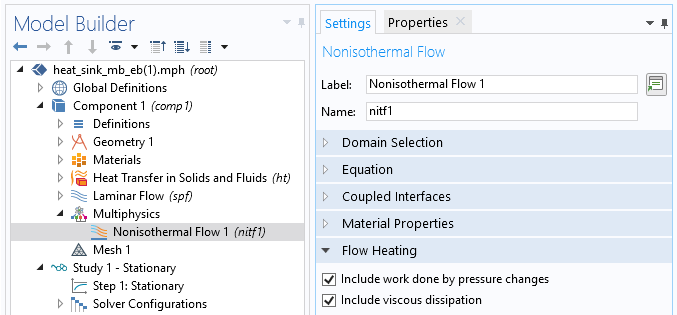
The Include work done by pressure changes and Include viscous dissipation features.
In case of a conjugate heat transfer analysis, which is when the heat transfer equation is solved together with the Navier-Stokes and continuity equations, the following total energy flux becomes the conserved quantity.
where E_0=E+\frac{1}{2}{\bf{u}}\cdot {\bf{u}} is the total internal energy.
The total energy flux accounts for convective, conductive, and radiation heat fluxes. It contains additional terms that represent the convective kinetic energy, \rho\frac{{\bf{u}}}{2}({\bf{u}}\cdot {\bf{u}}), and the convective stress energy, \sigma{\bf{u}}. The energy balance equation then takes the following form:
In a stationary study, this expression reduces to
For each quantity of this equation, a predefined global variable is available for postprocessing. The derived global evaluation values can be used to evaluate the variables. The table below summarizes the names of the different predefined variables of interest.
| Total Accumulated Energy Rate | \frac{d}{dt}\int_\Omega \rho E_0 \ dV | \mathrm{ht.dEi0Int} |
|---|---|---|
| Total Net Energy Rate | \int_{\partial\Omega} (\rho{\bf{u}}E_0-k{\bf{\nabla}} T+{\bf{q}}_\mathrm{rad}-\sigma{\bf{u}}) \cdot {\bf{n}} \ dS | \mathrm{ht.ntefluxInt} |
| Total Heat Source | \int_\Omega Q \ dV | \mathrm{ht.QInt} |
Therefore, the energy balance equation, written using the predefined variables in COMSOL Multiphysics, becomes
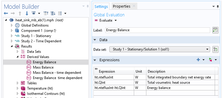
Use of derived global evaluation values to evaluate the energy rate of predefined variables.
At steady state, the total accumulated energy rate vanishes. The total net energy rate and the total heat source must balance. The results for the stationary study are shown below. The relative error is again much less than the relative solver tolerance.

Energy balance of a stationary analysis. The total net energy rate and total heat source must balance.
The energy rates are plotted below for the transient analysis. The total net energy rate increases progressively to finally reach its steady-state value, which balances the applied flux, 1 W, on the heat sink base. On the other hand, the total accumulated energy rate initially balances the total heat source and vanishes once the steady state is reached. Furthermore, the pink line denotes the energy balance absolute error; i.e., \mathrm{ht.dEi0Int} + \mathrm{ht.ntefluxInt}-\mathrm{ht.QInt}, which should be, in the best case, zero. The results show good agreement.
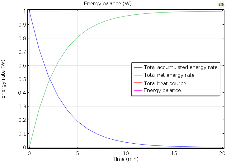
Energy rate versus time.
Concluding Remarks
We have discussed the theory of mass and energy conservation for static as well as transient conjugate heat transfer problems. We have also taken a look at how to calculate energy and mass balances with COMSOL Multiphysics in order to check the accuracy of simulation results. For this purpose, some useful derived value features have been introduced. Predefined energy rate variables are easy to use, and you can avoid handling the calculation of the energy rate expressions by yourself.
Although we have used a specific example to demonstrate the topics covered in this blog post, the demonstrated method can be extended to any conjugate heat transfer problem. For further reading about energy balances in COMSOL Multiphysics, please have a look at the Heat Transfer Module user’s guide.
Try It Yourself
Download the MPH file accompanying this blog post by clicking the button below, which will take you to the Application Gallery.
Editor’s note: This blog post was updated on 3/6/2019 to include new details and updated information.


Comments (10)
Vishwas Nesarikar
October 14, 2015Thank you for detailed explanation !
Hope to see similar detailed blogs on other topics as well.
Fabio Bocchi
October 15, 2015 COMSOL EmployeeHi Vishwas,
Thanks for your feedback. We appreciate it.
Fabio
Nawaz Ahmad
December 2, 2015Hi,
According to my observation based on working with COMSOL: COMSOL does not take into account the dispersive fluxes in mass balance, that is a major drawback. If you increase the dispersivity you have to face serious consequences in the form of mass balance error.
I hope COMSOL experts will give attention to mass balance errors related to dispersion.
Regards,
Nawaz Ahmad
KTH
Ali Mehrabifard
February 3, 2017Thank you for your practical note. I am using surface integral technique to compute the mass flux in my doublet system in which there are two cylindrical shape wellbores, one of which is injection and the other one is production in a porous media. I sat a constant injection rate for the injection wellbore, and I interested in calculating the production rate on the production wellbore. However, in such a calculation, there is a point that when I am calculating the mass flux for injection well it is far different from the imposed value which I already sat. Accordingly, the other calculation including production mass flux (rate) is not reliable and indeed logically they are far from the expected values. I found some solutions, since it was the problem that many users are being faced. One solution was to remesh the model, I did that for a simple 2D it was working, but for the 3D model, the RAM memory is not supporting the calculations (I am using a 32 GB RAM memory). The other solution is to impose the injection flux (rate) by Weak Constraint, in this sense, based on my best knowledge, Lagrangian Multiplier method which is using here is a method by which maximum and minimum of an objective function is being calculated when there is a constraint function and boundary conditions. I got confused, how Weak Constraint can help me out?
Is there any one who already modeled the wellbore in 3D with a line, if yes, how did u assign pressure value which can vary by depth?
Thanks in advance,
Ali
SNU
Caty Fairclough
February 6, 2017Hi Ali,
Thank you for your comments and interest in this blog post!
For your questions, I would suggest contacting our support team.
Online support center: https://www.comsol.com/support
Email: support@comsol.com
Best,
Caty
Katherine Sanchez
May 15, 2017Hi Fabio,
I did not understand how they got the mass balance results for the transient analysis, You could share the expression of mass balance
Best,
Katherine
Caty Fairclough
May 30, 2017Hi Katherine,
Thanks for your comment.
The mass balance is obtained through the “Derived values” in the image captioned “Step calculation for each mass flow rate term…”. Here, the expression for the normal mass flow (rho*u,n), which is the projection of the mass flow rate (rho*u) on the normal vector (n) to a boundary, is integrated both at the inlet and outlet boundaries. In addition, the accumulation of mass, d(rho)/dt, is integrated over the volume. The mass balance states that “in-out + accumulated = 0”.
So the three derived values: “Inlet mass flow rate” (in, surface integral), “Outlet mass flow rate” (out, surface integral), and “Volume mass flow rate” (accumulation, volume integral) are the three derived values required to calculate the error in the total mass conservation (mass balance).
Sunku Prasad J
January 1, 2018thanks for the details of energy balance.
I have one small doubt. How to perform energy balance COMSOL Multiphysics 4.3a ?.
chenchen lee
April 17, 2018Hi, Fabio Bocchi
The value I calculated from inlet and outlet are available, but for the volume mass flow rate for every steps, it is “zero”, I do not know why. Thank you very much!
Asmaa Ahmed
November 7, 2019Dear Fabio,
Thanks so much for the detailed explanation. But regarding the energy balance, if I am applying a heat flux on the top surface (on a boundary), in this case how can I calculate the Energy balance though the system?
Looking forward to your reply,
Many thanks,
Asmaa