
The Ray Optics Module extends the modeling capabilities of the COMSOL Multiphysics® software to include ray tracing simulation. This module makes it possible to accomplish advanced thermal, structural, and other studies of complex optical systems in an integrated software environment. The first step in a successful simulation is the creation of the model geometry. This blog post examines how to create a complex lens geometry, using the Petzval lens as an example.
Defining the Optical Prescription of a Complex Lens System
An example of a moderately complex optical system is a Petzval lens with a field-flattening lens. A multielement lens system with a focal length of 100 mm and a focal ratio of approximately f/2.4 is shown in the figure below.
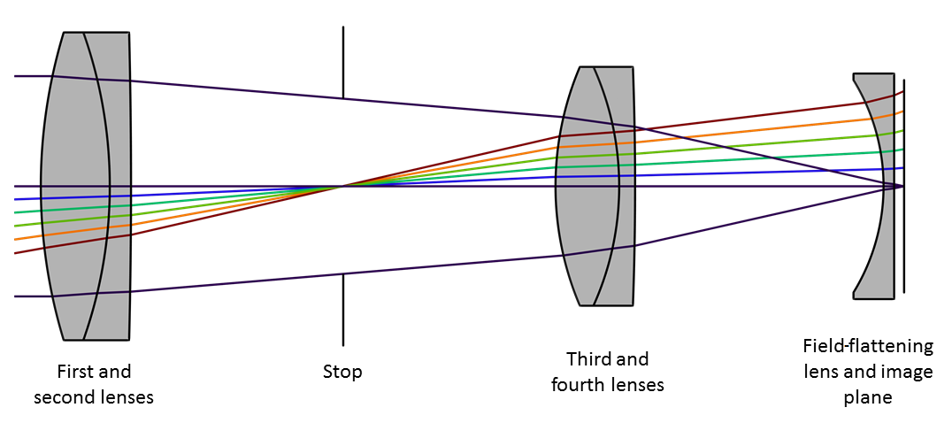
A Petzval lens that includes a field-flattening lens.
The optical prescription of this camera lens (as described in Ref. 1) is given in the following table. The geometry consists of two doublet lenses together with a field-flattening lens. Altogether, the rays refract across eight different surfaces. Two additional surfaces for the aperture stop and image plane are also shown.
|
Surface Index
|
Element Number
|
Name
|
Radius of Curvature (mm)
|
Thickness (mm)
|
Clear Radius (mm)
|
Material
|
|---|---|---|---|---|---|---|
|
0
|
N/A
|
Object
|
∞
|
∞
|
N/A
|
N/A
|
|
1
|
1
|
Lens 1
|
99.56266
|
13.00000
|
28.478
|
S-BK7
|
|
2
|
2
|
Lens 2
|
-86.84002
|
4.00000
|
26.276
|
S-BASF12
|
|
3
|
N/A
|
N/A
|
-1187.63858
|
40.00000
|
22.020
|
N/A
|
|
4
|
3
|
Stop
|
∞
|
40.00000
|
16.631
|
N/A
|
|
5
|
4
|
Lens 3
|
57.47191
|
12.00000
|
20.543
|
S-SK2
|
|
6
|
5
|
Lens 4
|
-54.61865
|
3.00000
|
20.074
|
S-SF5
|
|
7
|
N/A
|
N/A
|
-614.68633
|
46.82210
|
16.492
|
N/A
|
|
8
|
6
|
Lens 5
|
-38.17110
|
2.00000
|
17.297
|
S-SF5
|
|
9
|
N/A
|
N/A
|
∞
|
1.87179
|
18.940
|
N/A
|
|
10
|
N/A
|
Image
|
∞
|
N/A
|
17.904
|
N/A
|
Now, before we can perform a ray optics simulation with COMSOL Multiphysics and the add-on Ray Optics Module, it is necessary to create the model geometry. In the following section, we discuss some options for doing this.
Creating the Model Geometry for a Petzval Lens
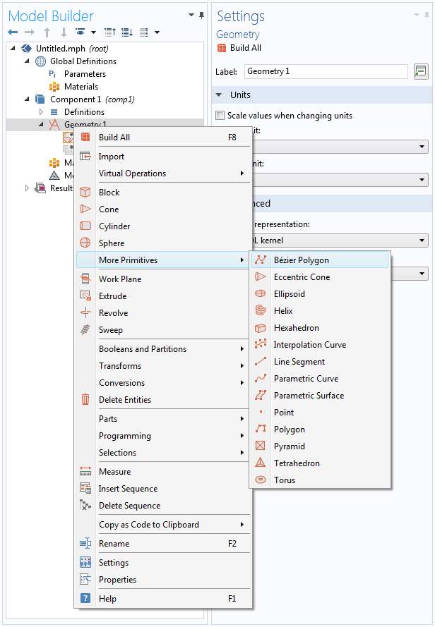
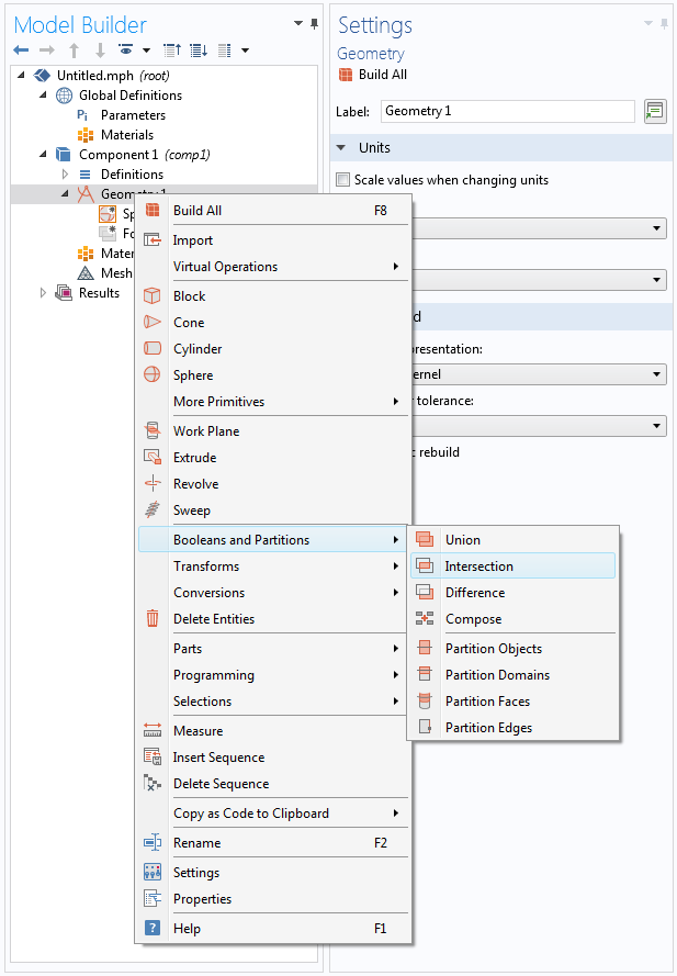
There are a variety of ways to create a model geometry in COMSOL Multiphysics. One possibility is to use combinations of built-in geometry primitives such as spheres, cylinders, polygons, and line segments. You can combine these simple geometric entities into more specialized shapes using Boolean, partition, transformation, and conversion operations.
Various geometry primitives (left) and Boolean and partition operations (right).
It will quickly become apparent that the creation of even the simplest optical geometry (such as a single lens) requires a significant number of operations. The full model geometry might require the same sequence of operations to be repeated several times with different numeric values. For example, different lenses might require the same steps but with different surface radii of curvature. To avoid setting up the same geometry sequence several times in a row, you can define some Geometry Parts. These parts are parameterized subsequences that can be called as if they are geometry primitives. By this means, each repetition of a lens can be accomplished using a Part Instance node, where the input parameters are the relevant details from the optical prescription.
An example of a user-defined geometry part can be seen below. In this case, the part defines a single lens with arbitrary front and rear radii of curvature as well as various definitions for the full, surface, and clear aperture diameters.
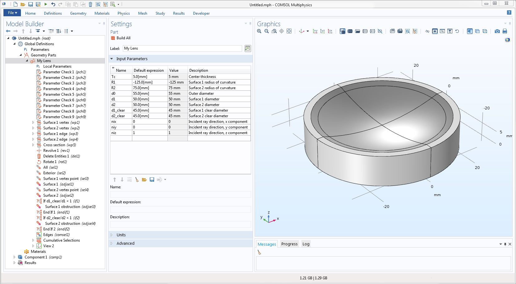
An example of a user-defined geometry part.
The Ray Optics Module includes a set of predefined parts for some of the most common shapes used in optical simulation, including a lens similar to the one shown above. These are available in the Part Libraries. The Part Library available in the Ray Optics Module is discussed in the following section.
Using the Part Library in the Ray Optics Module
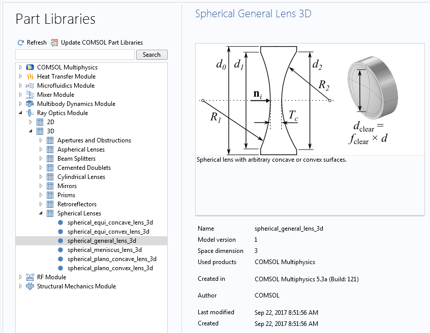
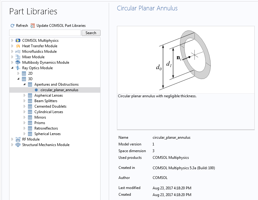
A variety of 2D and 3D parts have been created for use in the Ray Optics Module. One of the more advanced examples is the Spherical General Lens 3D (shown below in the left image). This part can be used to create a wide variety of lens forms, including any combination of concave and convex lens surfaces. Indeed, it is flexible enough that it can be used for all of the lenses in both a Petzval lens as well as a double Gauss lens. The Circular Planar Annulus part is also shown below. This part is a convenient way to create aperture stops and to define the image plane.
Examples of parts in the Part Library in the Ray Optics Module: Spherical General Lens 3D (left) and Circular Planar Annulus (right).
Parts found in the Ray Optics Module’s Part Library often contain one or more variants. These variants are intended to accommodate the use of the same basic part in a variety of ways. For example, the Spherical General Lens 3D can be specified either in terms of the clear aperture diameter or in terms of the clear aperture fraction. Other parts have variations that permit specifying either the central thickness or the edge thickness. It might also be possible to give the effective focal length (and refractive index) in place of the radius of curvature.
Loading the Optical Prescription Parameters into COMSOL Multiphysics®
We now have almost everything in place to create the Petzval lens model geometry. We proceed by inserting instances of the Spherical General Lens 3D and subsequently entering the geometry parameters (that is, the radii of curvatures, central thickness, and diameters) directly from the optical prescription table. However, this process can be simplified by reformatting the lens prescription so that it can be loaded in its entirety (for example, from a text file) into the Global Definitions node of the current model. That way, if you wish to adjust the optical prescription later, you can make all of the changes in one place. The optical prescription parameters for the Petzval lens can be seen below.
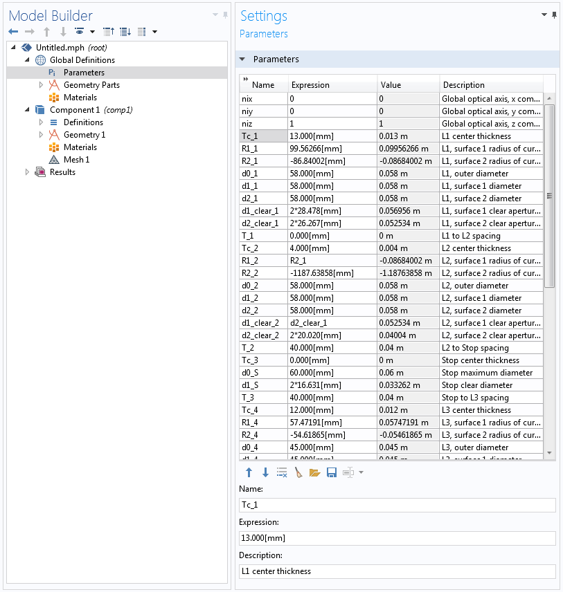
The optical prescription parameters for the Petzval lens model.
Having already loaded the two geometry parts from the Part Library (that is, the Spherical General Lens 3D and the Circular Planar Annulus parts), we insert the first element of the Petzval lens (“Lens 1”). The optical prescription parameters we defined above can be used as input parameters for the Part Instance node. Each lens parameter has been given a unique name (such as “Tc_1”, “R1_1”, “R2_1”, etc.) so that these values can be entered directly into the Expression fields. This process can also be simplified by loading a text file that contains definitions of the relevant expressions for each lens element.
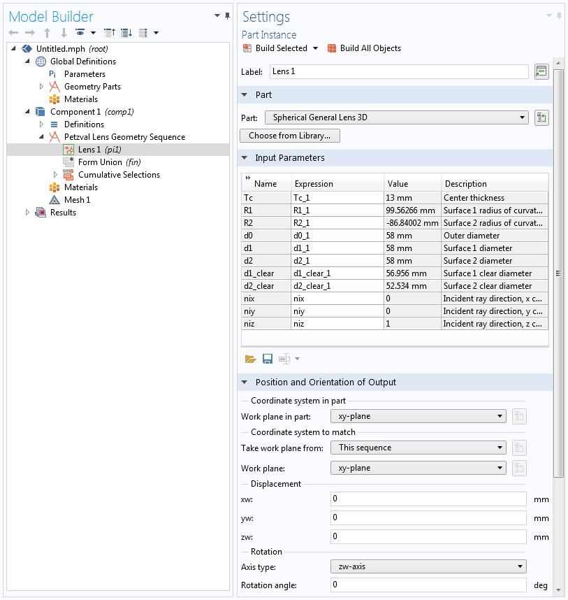
The first element (Lens 1) of the Petzval lens model geometry.
Note that in addition to allowing definitions of the surface clear diameters, the Spherical General Lens 3D part has parameters that can be used to specify the physical diameters of each surface as well as the overall lens diameter. This capability makes it possible to construct a geometry that closely matches the geometry that will be manufactured. For example, this makes it easier to set up a high-fidelity model that includes the structural and thermal effects on the lenses and the surrounding barrel.
Next, as shown below, we insert a second instance of the Spherical General Lens 3D, which is used to define “Lens 2”. This element must, of course, be placed in the correct absolute location within the model geometry. A standard optical prescription usually specifies the distance from the entrance surface of the current lens to the exit surface of the preceding lens. Therefore, the definition of the Spherical General Lens 3D part includes work planes that locate the entrance and exit vertices of each lens surface. Each subsequent lens part instance can then be placed with respect to the work plane located on the exit vertex of the preceding lens. As demonstrated below, “T_1” is the distance between the exit surface of Lens 1 and the entrance surface of Lens 2. (In this case, the separation happens to be 0. Therefore, a doublet lens is created, but the same principle applies for any given separation.)
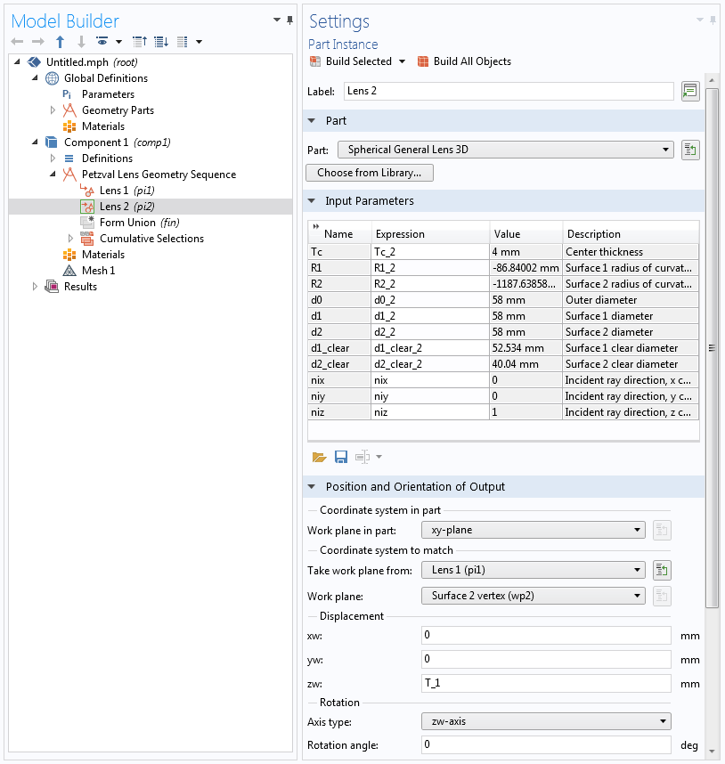
The second element (Lens 2) of the Petzval lens model geometry.
Putting It All Together: Ray Tracing the Petzval Lens
Along with the lens elements, additional surfaces can be added to the Petzval lens model geometry that define the aperture stop and the image plane. For convenience, the complete model geometry can be saved as a geometry sequence so that it can be used in other COMSOL Multiphysics simulations. The full model (neglecting stray light apertures) is shown in the figure below. Here, we see that a unique feature of the Ray Optics Module is its ability to perform a ray trace on a fully meshed geometry. The same mesh can be used to solve for other quantities like temperature and structural displacement in the lens geometry, streamlining the setup of bidirectionally coupled multiphysics models.
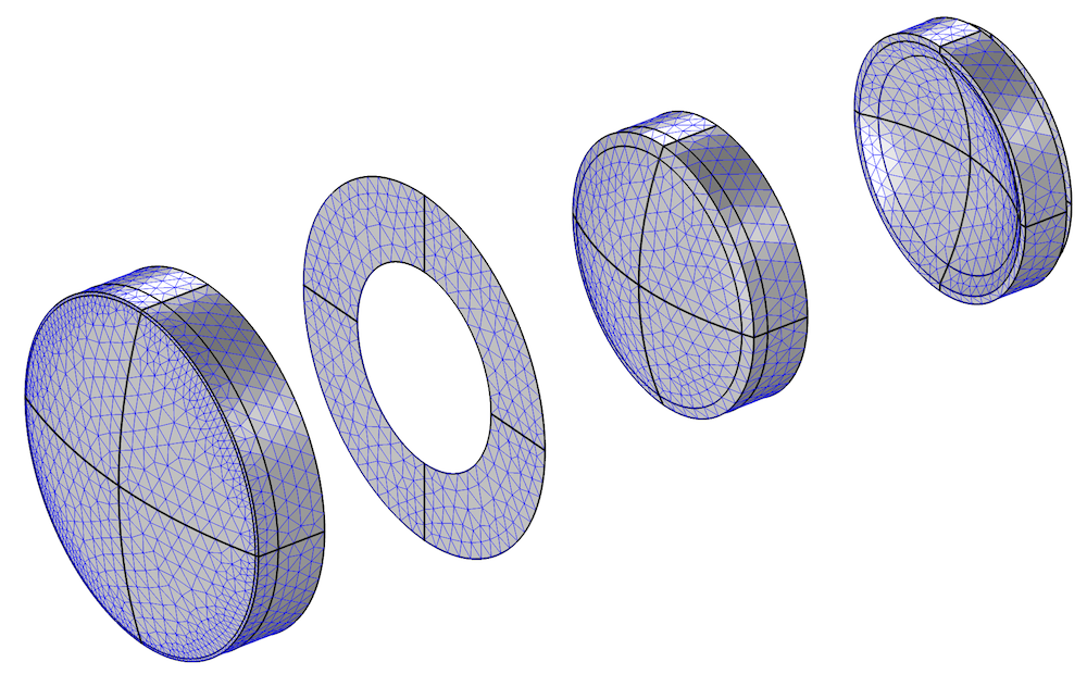
The completed model geometry for the Petzval lens, showing the surface mesh elements.
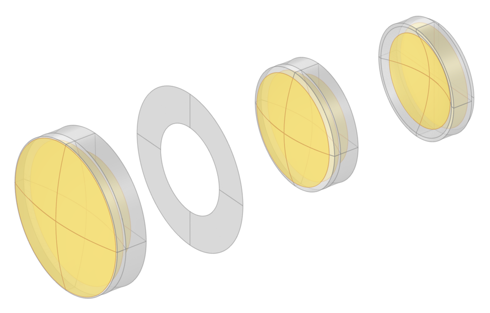
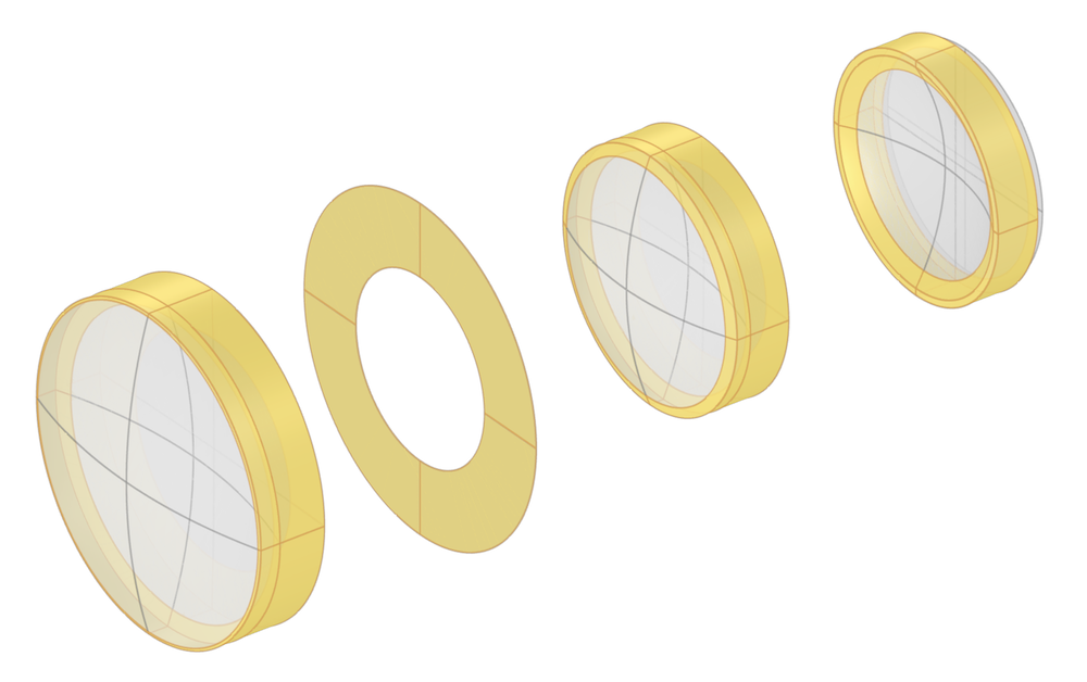
Other features can be built into the definition of the parts. For example, work planes have also been defined in the Spherical General Lens 3D part and indicate the location of the front and rear edges of the lens. These work planes can be used to precisely locate apertures for blocking stray light or to locate mechanical mounting features. In addition, selections have been defined, separating the clear apertures, obstructions, and edges of each lens part. These selections can be used to quickly define the various physics features required for a geometrical optics simulation, as seen in the figures below.
The selections used in the Petzval lens to define the clear apertures (left) and the obstructions (right).
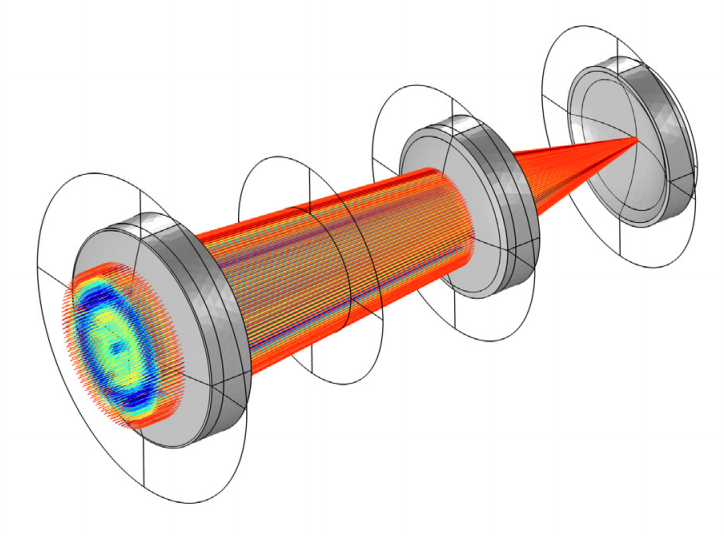
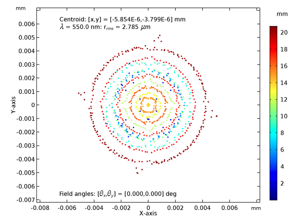
For this ray tracing example, we generated results via a grid-based ray trace at a single wavelength (550 nm) and field angle (on-axis). The results shown below make use of custom color expressions, added during postprocessing for better visualization. The color expression of the left plot (the ray trace) is based on the ray locations on the image plane. The color expression of the right plot (the spot diagram) is based on the ray locations at the entrance pupil. Each of these color expressions makes it possible to easily visualize the relative contribution of the rays at the entrance pupil to the final image quality.
Ray trace (left) and spot diagram (right) of the Petzval lens.
Next Steps
The example featured above demonstrates how to create an optical geometry prior to performing a ray tracing simulation. To try this model yourself, click the button below.
Learn More About Modeling Lenses
- Check out another lens example: Double Gauss Lens (Parametric Sweep)
- Read these related blog posts:
Reference
- M.J. Kidger, Fundamental Optical Design, SPIE Press, 2001.



Comments (5)
Shenglin Ye
October 25, 2018Hi Stuart,
Today, I attended a webinar hosted by you: “Structural-Thermal-Optical Performance (STOP)Analysis with COMSOL Multiphysics”. Thanks for your detailed explanation and this seminar is very useful for me. Then, I want to download the comsol file ” petzel-lens-stop analysis”. However, I cannot find in the Application library even I updated the current library database. Could you do me a favor to point out where I can find this file.
Thanks!
Shenglin
Stuart Barnes
October 26, 2018 COMSOL EmployeeHi Shenglin,
I’m glad you found the webinar useful. The petzval_lens_stop_analysis.mph (and petzval_lens_stop_analysis_isothermal.mph) models can be found in the Structural_Thermal_Optical_Performance_Analysis folder in the Ray Optics Module application library.
Note that these models were introduced in v5.4 and can only be accessed once you have updated to this version.
The model and documentation can also be found here: https://www.comsol.com/model/petzval-lens-stop-analysis-63831
Regards, Stuart
Shin Jun Hyuk
March 18, 2020Hi, Stuart,
I’m looking for how to express ‘radius of curvature’ in COMSOL and I just saw your blog.
I think it will be helpful for my simulation.
I would like to ask how did you express radius of curvature in you blog. I tried to find radius of curvature but i couldn’t.
Thanks
Best regards
Shin
Stuart Barnes
March 20, 2020 COMSOL EmployeeHi Shin,
Thank you for your interest in our blog. In the example of the “Petzval Lens”, which uses the built-in “Spherical Lens 3D” part from the Ray Optics Parts Library, the radius of curvature of a lens can be entered in the Input Parameters for each part instance; that is, in the rows “R1” and/or “R2”. If the prescription you are following lists the curvature (1/R) instead, just enter the inverse.
As noted in the blog, in this example the lens prescription was first loaded as a table of Parameters. This way, we can use expressions such as “R1_1″, R1_2” to define the lens parameters.
Regards, Stuart.
Anju .
August 9, 2021Hii
Thank You for the informative blog. I would like to know how to set conditions for using lens surface as reflective only.