

Irregular shapes can come in several different formats. In our blog series on modeling irregular shapes, we have explored different methods of handling irregular shapes in the COMSOL Multiphysics® software. In this blog post, we add to this series by covering how to take a set of images and loft them into a solid.
Editor’s note: The original version of this post was published on September 20, 2017. It has since been updated to reflect new features and functionality in COMSOL Multiphysics®.
An Example of an Irregular Shape: The Human Head
One possible format when working with scanned data is images of slices produced by an MRI or CT scan. In this example, let’s look at a case where we have cross-sectional images of a human head.
In short, the procedure includes:
- Creating work planes by running code in the Java Shell
- Creating curve objects of each of the images using a built-in add-in
- Lofting the curves into a solid
- Hiding unnecessary edges to produce a consistent shape
Now, let’s look at each step in more detail.
Creating Work Planes
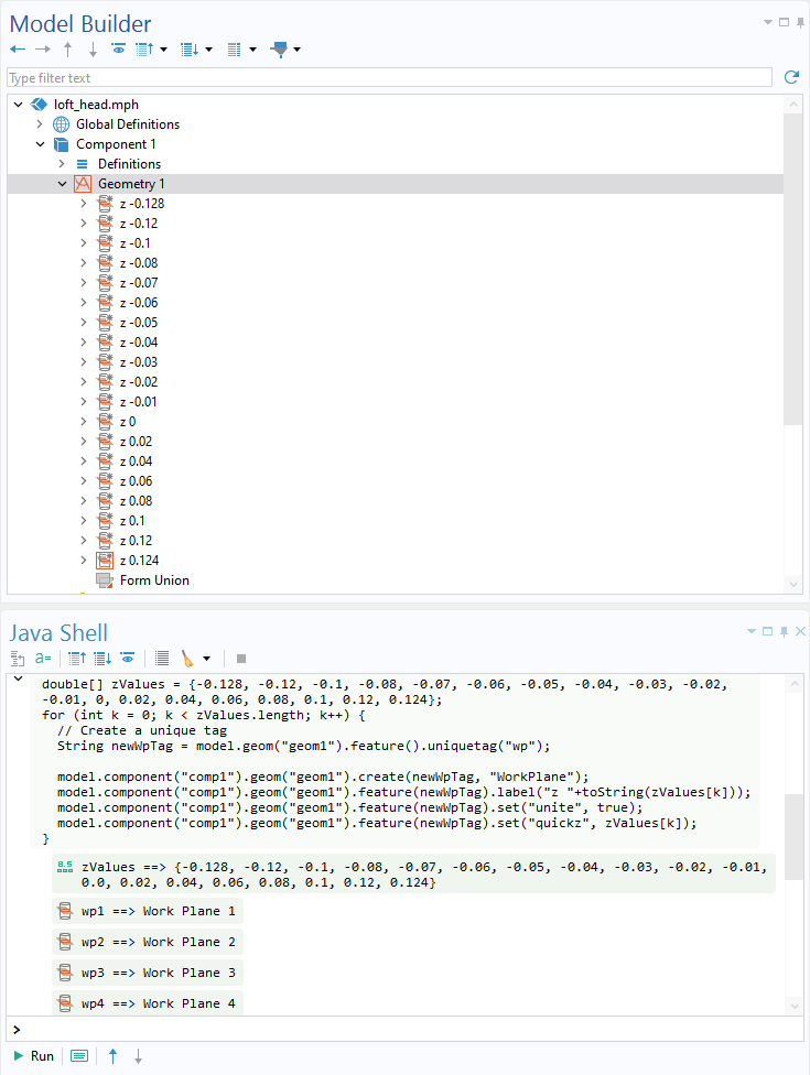
In this example, we have 19 cross-section images of a head, which means that 19 Work Plane features are needed, positioned at the correct z-coordinate. This can easily be done by running the following code in the Java Shell:
double[] zValues = {-0.128, -0.12, -0.1, -0.08, -0.07, -0.06, -0.05, -0.04, -0.03, -0.02, -0.01, 0, 0.02, 0.04, 0.06, 0.08, 0.1, 0.12, 0.124};
for (int k = 0; k < zValues.length; k++) {
  String newWpTag = model.geom("geom1").feature().uniquetag("wp");


  model.component("comp1").geom("geom1").create(newWpTag, "WorkPlane");
  model.component("comp1").geom("geom1").feature(newWpTag).label("z "+toString(zValues[k]));
  model.component("comp1").geom("geom1").feature(newWpTag).set("unite", true);
  model.component("comp1").geom("geom1").feature(newWpTag).set("quickz", zValues[k]);
}
Please note that in the model available for download at the end of this blog post, the code has been saved in a method. Running a method from the Developer ribbon tab will, in this case, produce the same result as running the code from the Java Shell.
Importing Images and Creating Curves
By using the built-in Image to Curve add-in on every image, one Interpolation Curve feature is added to each work plane, resulting in a total of 19 curve objects. To learn more about this add-in, please check out our blog post "How to Use an Add-In to Convert Images to Geometry Models".
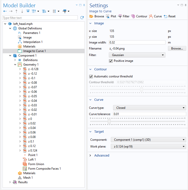 The settings for the Image to Curve add-in.
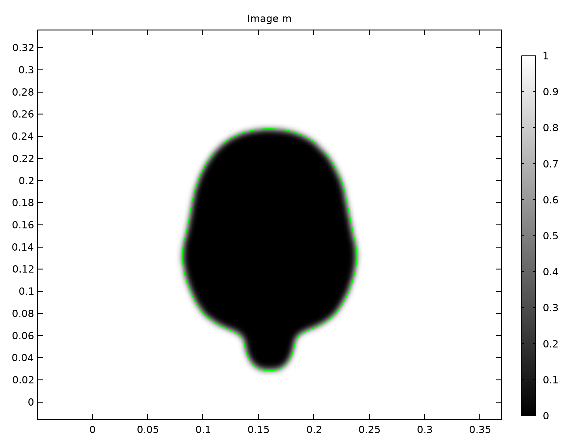 A cross-sectional image of the head, showing the curve at the contour threshold of 0.6 plotted in green.
The Contour threshold is fixed at a value of 0.6 to ensure that all contours are scaled equally. The Closed curve setting is used to ensure that the created curve objects are indeed closed and that the first- and second-order derivatives are continuous everywhere. In COMSOL Multiphysics®, lofting a closed curve produces a solid object, while lofting an open curve produces a surface. In this example, the default Relative tolerance of 0.001 is used for all curves except for the last one (z 0.124), where it has been increased to 0.01 to get a smoother curve. Lastly, a point is added at the top of the head. If you have curve coordinate data instead of images, you can import this data directly into the Interpolation Curve feature without the need for the add-in.
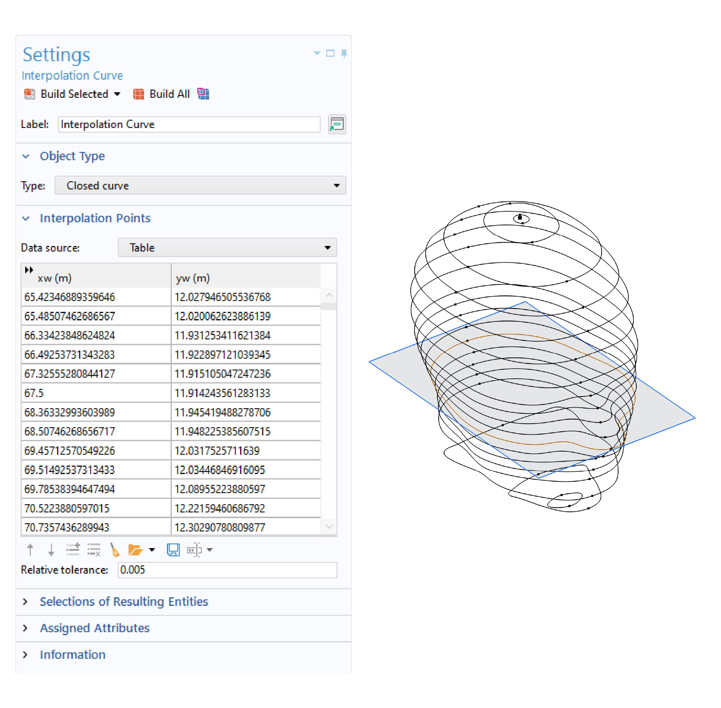
The Settings window for the Interpolation Curve feature (left) and all of the curves and points representing the outer shell of a head (right). The gray surface represents the work plane at the z coordinate of -0.04 and the curve that lies in the work plane is highlighted in yellow.
Considerations for Lofting Solids
Now that we have the curve objects that define the outline of each cross section of the head, we can create the solid shape with the Loft operation. The Loft operation is one of the geometry modeling tools included in the Design Module. Before setting up the Loft operation, we need to make sure that the curve objects are suitable as profiles for lofting. Lofting curves or surfaces to a solid requires the different profiles to have the same number of edges and points. The Partition Edges operation can be used to ensure an equal number of edges and points, as discussed below. The exception is the first and last objects (called the start and end profiles), which can be curve objects with a different number of edges than the intermediate profiles, or can be points.
A closed interpolation curve has two vertices. So, the criterion mentioned above — to have the same number of edges and points of the intermediate objects — is already fulfilled, as all of the created curves have two edges. However, where these points are placed on the profile objects is also important. When the loft works its way through the curves, it connects all of the points with edges in the direction of the loft. If the points are not positioned along a fairly straight line, the resulting surfaces might become distorted. The edges can be manually partitioned to accomplish a good representation of all of the surfaces. It is not necessary in this example, but if needed, a Partition Edges operation can be added to partition the edges by projecting a selected vertex.
To verify that the geometry objects have the same number of edges and points, we click the Select Objects button above the Graphics window, select a curve object in the Graphics window, and then click the Measure button in either the Geometry or Mesh tab. The output of this measurement is written to the Messages log.
Lofting the Solid
As the points are already roughly aligned in this example, it is time to create the solid. The Loft feature contains several options, but we only use the most straightforward procedure here: adding the point and all of the curve objects of the head in the Profile objects list. The start and end profiles are determined automatically by the Loft operation. There are many collapsed sections in the Loft settings window that can be used to fine-tune the loft. For example, to specify the direction of the loft or to further control the shape using guide curves. The settings in the collapsed sections are not used in this example.
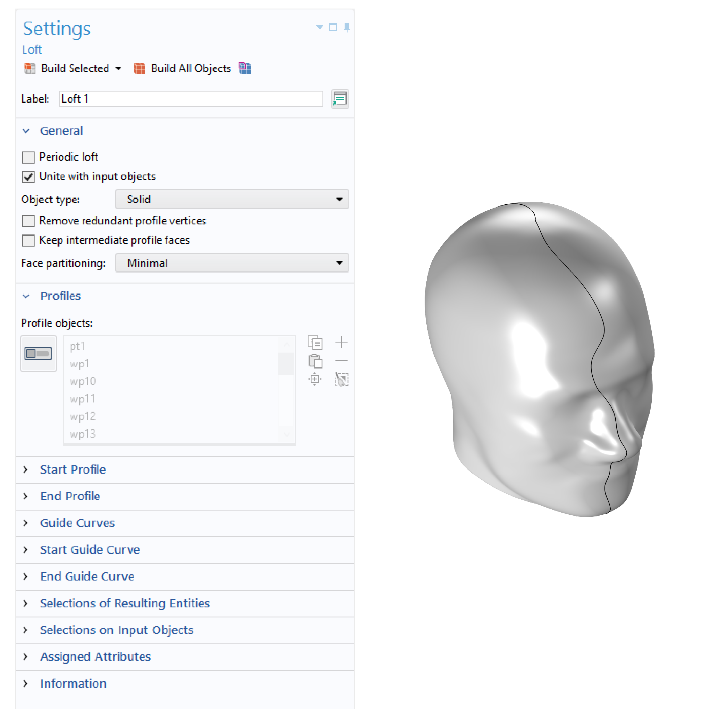 The settings window of the Loft operation (left), showing the input Profile objects, which is the only input used in this example. The right image shows the resulting solid head.
Surface Partitioning
A surface or solid object lofted from closed continuous profile curves has at least two seams that go through the vertices of the profile curves, creating two or more boundaries. More seams may be introduced by the operation, depending on the alignment of the vertices on the different curves. If the profile curves have discontinuous tangents, additional seams are introduced and go through these points. No additional seams are introduced when using the default setting Face partitioning: Minimal in the Loft operation (see the image above), as is the case in this example.
If we want the lofted surface to be more partitioned, the partitioning options Column and Grid can be used. The first option divides the surface along each vertex in the profile curves, while the latter also adds the profile curves. Another possibility is to partition the surfaces with other geometry objects using Boolean and partition operations. This can create boundaries to assign boundary conditions. On the other hand, if we want to have a more clean appearance, we can use Virtual Operations to create composite faces. Form Composite Faces is one feature that can be used for this purpose, but Ignore Edges also gives the same end result.
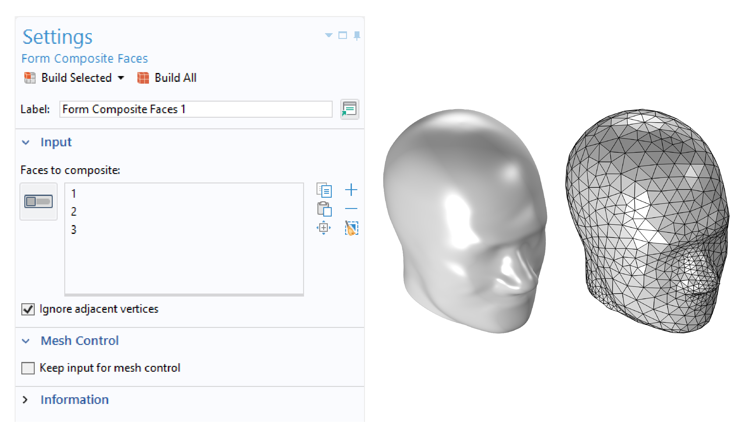 By adding the edges (shown in the previous image) to a Form Composite Faces operation (left), the final geometry gets a smooth look (middle). On the right-hand side, a meshed version of the head is shown.
Next Steps
This blog post has discussed the possibility of creating curves from imported images and then lofting these curves into a solid object. Download the file used to create the example featured by clicking the button below.
Further Learning
- Try out another model example that uses the Loft operation:
- Read our other posts in our blog series on modeling irregular shapes:
- Learn more about customizing the Model Builder workflow in this blog post:


Comments (9)
峰 程
September 21, 2017Hi. It is a useful blog about building geometry and there is something I can not understand.
In the section of “Partitioning the Edges of Curves”, you did not partition all of the curves.
Is it not necessary?
And what is the trick to pick the curves to be partitioned?
Thank you.
Hanna Gothäll
September 26, 2017 COMSOL EmployeeGreat to hear that the blog post is of use to you! There are two criteria to fulfill: (1) The vertices should be positioned along a fairly straight line in the sweep direction. (2) The curves need to have the same number of vertices. The number of vertices will be modified for the curves until both criteria are both fulfilled.
Feel free to send in your MPH file to support@comsol.com and we can give more specific advice on how to select the curves to partition.
Xuewei Zhao
October 7, 2017Hi. This blog is very helpful for me. Now I have another issue. Which software can give the text files containing the coordinate data of the curves? In addition, for the case of my work, the solid has a close inner surface. Can you give me some advices? Thanks a lot!
Hanna Gothäll
October 18, 2017 COMSOL EmployeeThe Sectionwise format is a format which is native of COMSOL Multiphysics. However, by inspecting a text file exported from COMSOL Multiphysics, you might be able to create a script which can translate your data to this format. For surfaces, you could import DXF files into 2D Workplanes. There are other possibilities as well, so please send in your question along with your files to COMSOL Support, support@comsol.com, so that we can look into your specific case.
Xuewei Zhao
October 18, 2017Hanna Gothäll@
Thank you for your reply. Sorry, I did not described my problem in detail.
I will built a geometry model of an irregular-shape food (dumpling) which is composed of two domains, i.e. core and wrapper. After MRI or CT scans (I have not do this work), series of 2D images will be obtained. I want to built a geometrical model of the dumpling according the procedure suggested in your above blog. The Sectionwise text files containing the (x, y, z) coordinates of the inner and outer boundary curves are necessary for building the geometry. I do not know how to get the Sectionwise format files form the MRI or CT images. I guess that Matlab (with image processing toolbox) live-linked with COMSOL was used in your procedure. But, I know very little about Matlab. Can you tell me the steps for obtaining the Sectionwise text files?
Xuewei Zhao
October 18, 2017Hanna Gothäll@
Thank you for your reply. Sorry, I did not described my problem in detail.
After MRI or CT scans (I have not do this work), series of 2D images will be obtained. I want to built a geometrical model of the dumpling (a chinese food, which is composed of two domains, i.e. core and wrapper) according the procedure suggested in your above blog. The Sectionwise text files containing the (x, y, z) coordinates of the inner and outer boundary curves are necessary for building the geometry. I do not know how to get the Sectionwise format files form the MRI or CT images. I guess that Matlab (with image processing toolbox) live-linked with COMSOL was used in your procedure. But, I know very little about Matlab. Can you tell me the steps for obtaining the Sectionwise text files?
Hanna Gothäll
October 23, 2017 COMSOL EmployeeTo get the data files for this blog post, I exported the data of contour plots to text files on the Sectionwise format.
Shisir Mia
May 5, 2018Hi, at present I am using Comsol 5.2 , so if you share the compatible loft_head.mph file for Comsol 5.2 to me. I will be very grateful to you. Thanks in advance…
Hanna Gothäll
May 9, 2018 COMSOL EmployeeHi Shisir,
Unfortunately, the model file associated with this blog post is not available in version 5.2. Sorry for the inconvenience