
On a bright evening in 1669, Professor Erasmus Bartholinus looked through a piece of an Icelandic calcite crystal he had placed onto a bench. He observed when he covered text on the bench with the stone, it appeared as a double image. The observed optical phenomenon, called birefringence, involves a beam of light that splits into two parallel beams while emerging out of a crystal. Here, we demonstrate a modeling approach for this effect.
Understanding Anisotropic Materials
The beam of light that Erasmus Bartholinus observed traveling straight through the crystal is called an ordinary ray. The other light beam, which bends while traveling through the crystal, is an extraordinary ray. Anisotropic materials, such as the crystal from the stone and bench experiment described above, are found in applications ranging from detecting harmful gases to beam splitting for photonic integrated circuits.
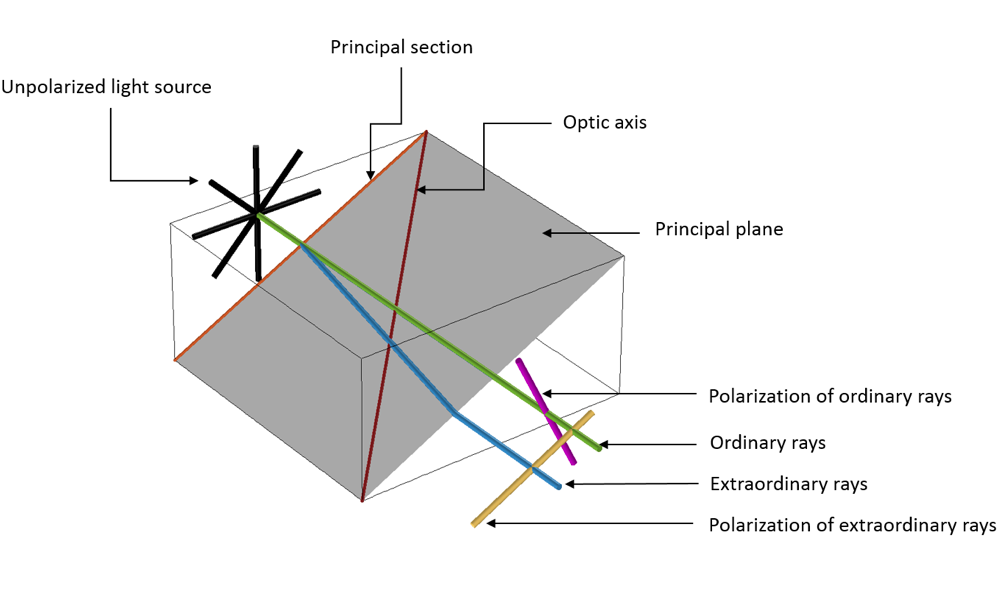
Ordinary and extraordinary rays traveling through an anisotropic crystal.
In a physical context, when an unpolarized electromagnetic beam of light propagates through an anisotropic dielectric material, it polarizes the dielectric domain, leading to a distribution of charges known as electric dipoles. This phenomenon leads to induced fields within the anisotropic dielectric material, wherein two kinds of waves experience two different refractive indices (ordinary and extraordinary).
The ordinary wave is polarized perpendicular to the principal plane and the extraordinary wave is polarized parallel to the principal plane, where the principal plane is spanned by the optic axis and the two propagation directions in the crystal. Because of this behavior, the waves propagate with different velocities and trajectories.
Introducing Anisotropy Within Silicon Waveguides
In a previous blog post, we discussed silicon and how its derivative, silicon dioxide, is used extensively in photonic integrated chips due to its compatibility with the CMOS fabrication technique. Bulk silicon, which has an isotropic property, is used to develop prototypes for photonic integrated chips. However, due to unique optical properties such as splitting beams and polarization-based optical effects, anisotropy comes into play at a later stage.
Anisotropy in silicon photonics occurs unintentionally due to the annealing process while fabricating the waveguide. The difference in thermal expansion between the core and cladding causes geometry mismatch due to stress optical effects, which results in effects such as mode splitting and pulse broadening. Anisotropy could also be intentionally introduced by varying the porosity of silicon dioxide. This enables researchers to work with a range of effective refractive indices from silicon dioxide (n ~1.44) to air (n ~1), giving them the edge to perform very sensitive optical sensor applications.
Optical Modes of Propagation
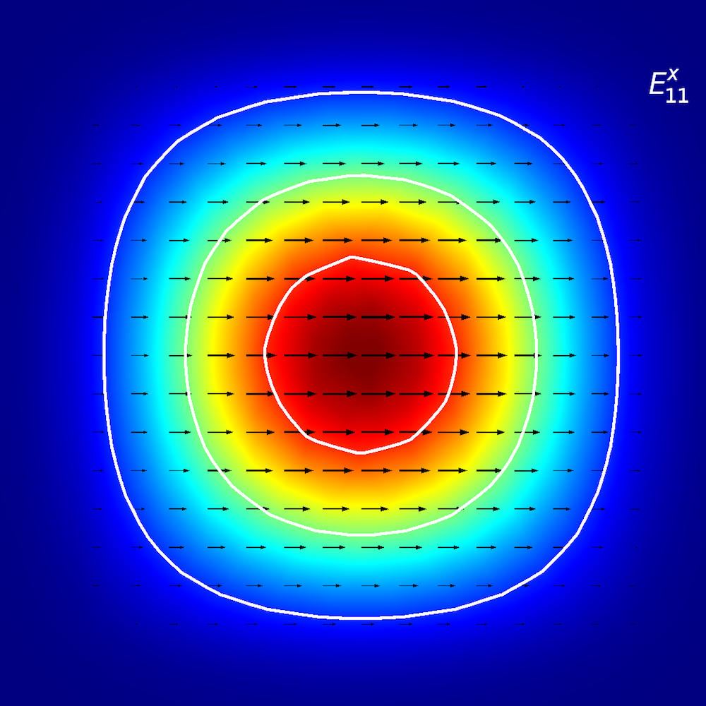
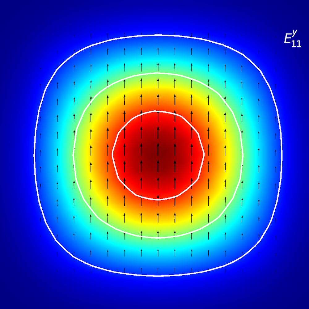
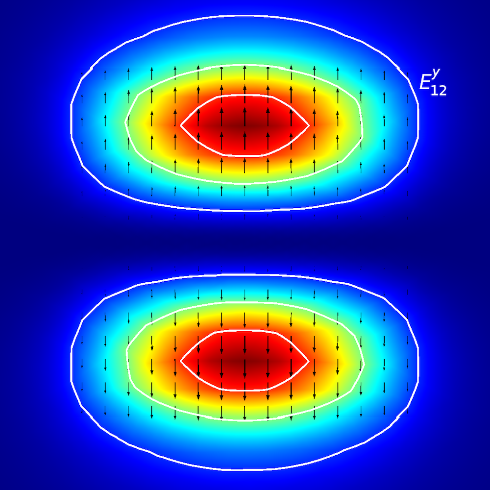
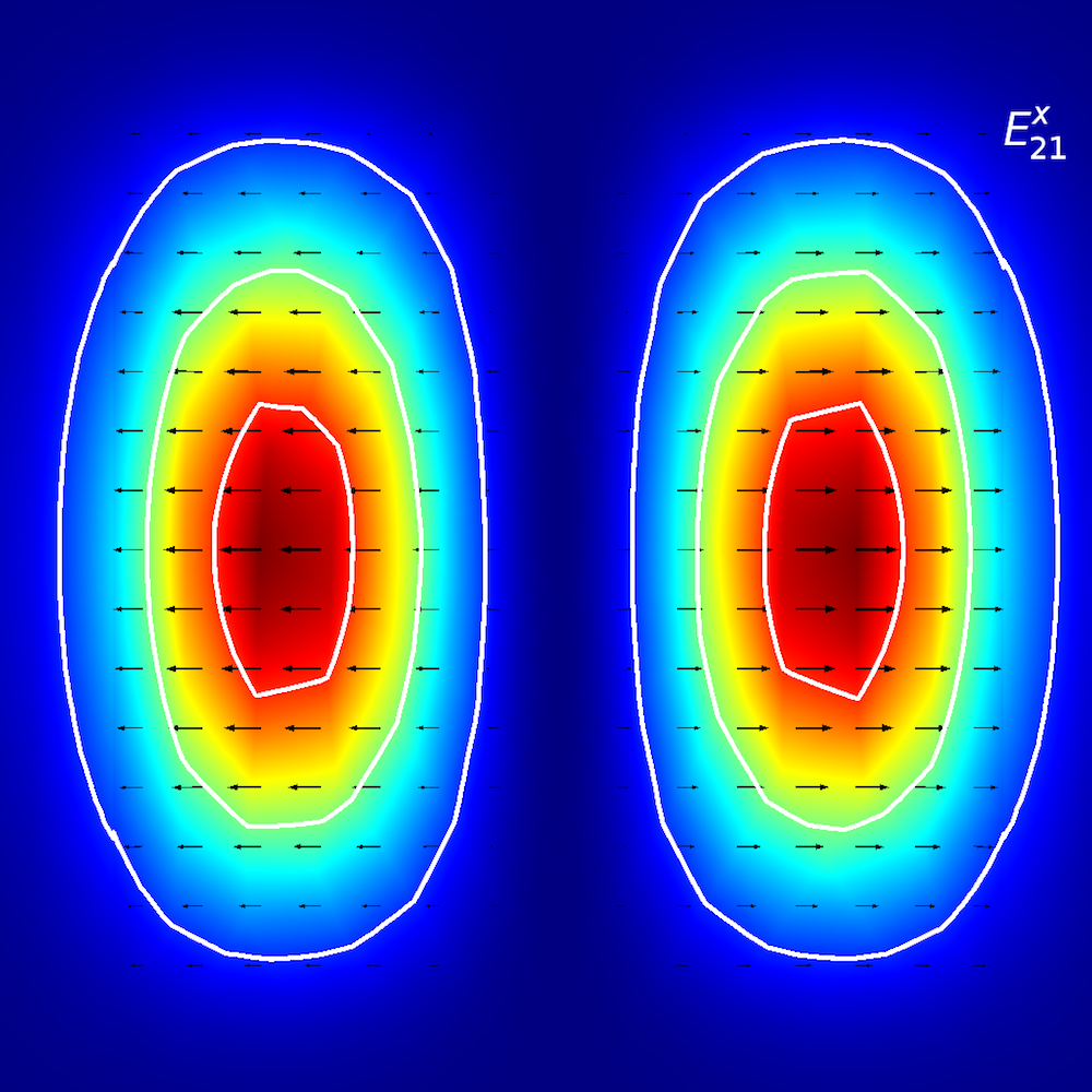
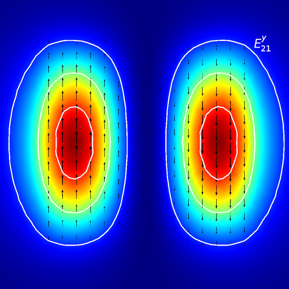
To perform qualitative analyses of anisotropic media, researchers investigate how optical energy propagates within planar waveguides (also known as modes of propagation). In planar waveguides, we define modes using E^{x}_{p,q} and E^{y}_{p,q} terminology (Ref. 2), where x and y depict the direction of polarization and p and q depict the number of maxima in the x– and y-coordinates.
Picture it this way: You are walking on an E^{x}_{2,1} “landscape” (as shown below). The “winds” (polarization) are along the ±x direction, and you encounter two distinct peaks when traveling from the –x to +x direction. When you move from the –y to +y direction, you observe both of the peaks simultaneously.
Mode analysis of the planar waveguide. Top row, left to right: E^{x}_{1,1} and E^{y}_{1,1}. Middle row, left to right: E^{x}_{1,2} and E^{y}_{1,2}. Bottom row, left to right: E^{x}_{2,1} and E^{y}_{2,1}. The arrow plot represents the electric field; contour and surface plot represent out-of-plane power flow (red is high and blue is low magnitude).
Analyzing Anisotropic Structures in the COMSOL Multiphysics® Software
Before launching a beam of light through a waveguide using a laser source, it is important to know which optical modes could persist within a specified core/cladding dimension of the waveguide. Performing a mode analysis using a full vectorial finite element tool, such as the COMSOL Multiphysics® software, could be very helpful to qualitatively and quantitatively analyze the optical modes and dispersion curve respectively.
Introducing Diagonal Anisotropy
Performing a modal analysis on any isotropic material requires the definition of a single complex value, while in the case of an anisotropic material, a full tensor relative permittivity approach is required. The electric permittivity essentially relates the electric field with the material property. Here, tensor refers to a 3-by-3 matrix that has both diagonal (\epsilonxx, \epsilonyy, \epsilonzz) and off-diagonal (\epsilonxy, \epsilonxz, \epsilonyx, \epsilonyz, \epsilonzx, \epsilonzy) terms as shown below.
\epsilon_{xx}&\epsilon _{xy}&\epsilon _{xz}\\
\epsilon _{yx}&\epsilon _{yy}&\epsilon _{yz}\\
\epsilon _{zx}&\epsilon _{zy}&\epsilon _{zz}\\
\end{bmatrix}
However, for all materials, you can find a coordinate system in which you only have nonzero diagonal elements in the permittivity tensor, whereas the off-diagonal elements are all zero. The three coordinate axes in this rotated coordinate system are the principal axes of the material and, correspondingly, the three values for the diagonal elements in the permittivity tensor are called the principal permittivities of the material.
There are basically two kinds of anisotropic crystal: uniaxial and biaxial crystal. With a suitable choice of coordinate system, where only the diagonal elements of the permittivity tensor are nonzero, in terms of optical properties, uniaxial crystal considers only the diagonal terms, that is \epsilonxx = \epsilonyy = (no)2, \epsilonzz = (ne)2, where no and ne are the ordinary and extraordinary refractive indices. However, when \epsilon_{xx}\neq \epsilon_{yy} \neq \epsilon_{zz}, it is known as a biaxial crystal.
To put this argument into a modeling perspective, we can extend the buried rib waveguide example from this blog post on silicon photonics design. We can perform a modal analysis on the 2D cross section of the waveguide with the square core and cladding length of 4 um and 20 um, respectively (shown below). The operating wavelength for all the cases is considered as 1.55[um].
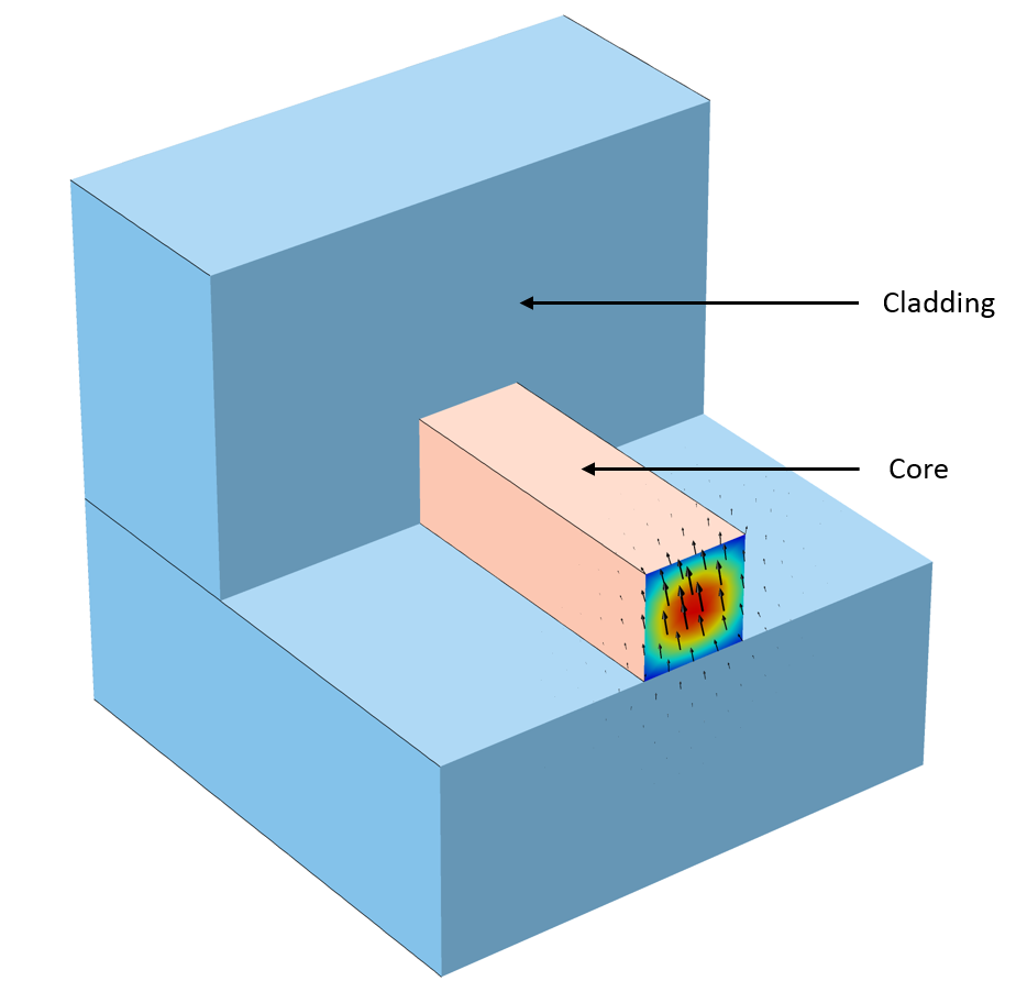
Schematic of 3D buried rib optical waveguide where the mode analysis was performed at the inlet 2D cross section. The intensity plot and arrow plot representing the mode and polarization of E-fields respectively.
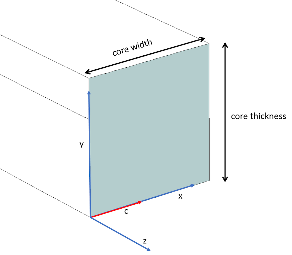
Core of the rib waveguide depicting the optic axis (red) along the x-axis and the principal axis (blue).
In the classic case of a uniaxial material, we assume the optic axis (i.e., c-axis) is along the principal x-axis (as shown above) and consider the diagonal relative permittivity \epsilonyy and \epsilonzz terms (which are orthogonal to the c-axis) as the square of ordinary refractive index (~1.51992 ~ 2.31). The \epsilonxx component element that is along the c-axis is considered as the square of extraordinary refractive index (~1.47992 ~ 2.19) (as per Ref. 3). In addition, the off-diagonal terms are considered zero (as shown below) and the cladding has an isotropic relative permittivity (~1.43182). The optical modes derived are the 6 modes shown above. Note the difference in the refractive indices: “nxx – nyy” is known as birefringence, where nxx = \sqrt{\epsilon_{xx}} and nyy = \sqrt{\epsilon_{yy}}.
\begin{bmatrix}
2.19 & 0 & 0 \\
0 & 2.31 & 0\\
0 & 0 & 2.31\\
\end{bmatrix}
Relative permittivity tensor with diagonal elements.
Dispersion Curves
By evaluating the optical modes, we can visually comprehend the behavior of the optical waveguide. However, the dispersion curves could also be handy for performing quantitative analyses. A dispersion curve represents the variation of the effective refractive index with respect to the length of the waveguide or the operating frequency.
Diagonal Anisotropy
A modal analysis is performed while parametrically sweeping the length of the waveguide from 0.5 um to 4 um to derive the dispersion curve for the anisotropic core, as shown in the figure below. We assume the earlier case stated, with diagonal anisotropy terms of the core (i.e., \epsilonxx = 2.19, \epsilonyy = \epsilonzz = 2.31, and all of the off-diagonal elements are zero). The results are compared with Koshiba et al. (Ref. 3).
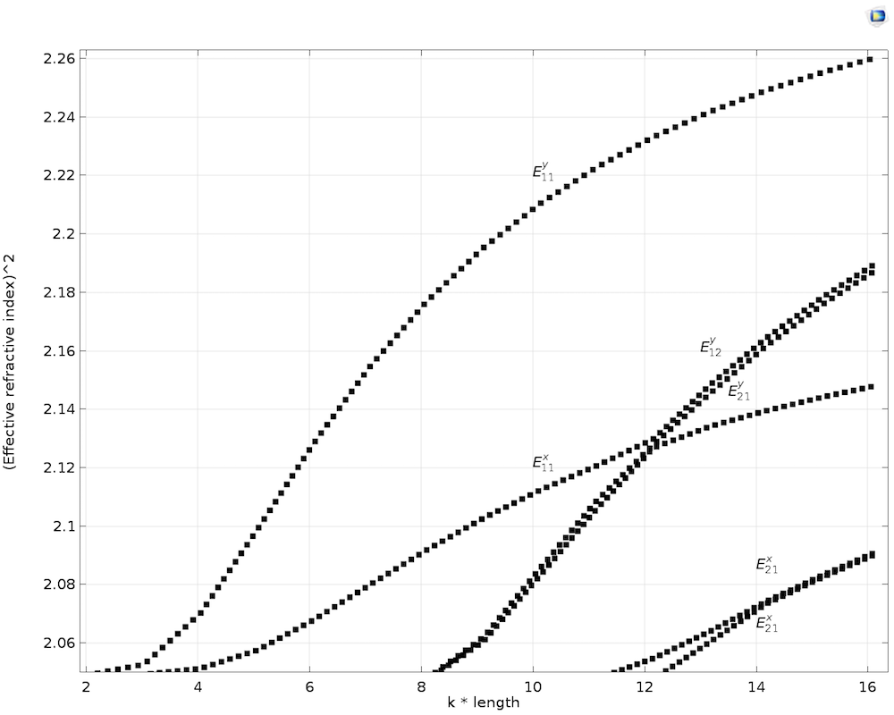
Dispersion curve with transverse anisotropic core.
Off-Diagonal Transverse Anisotropy (XY Plane)
When the optic axis (i.e., c-axis) lies in XY plane and makes an angle of \theta with the x-axis, the diagonal components \epsilonxx, \epsilonyy, \epsilonzz and off-diagonal components \epsilonxy and \epsilonyz are nonzero, while the rest of the components are zero. The full relative permittivity tensor could be evaluated by using the rotation matrix [R] as shown below, where the rotation matrix [R] is specifically for rotating the c-axis in the XY plane. \epsilonxx is the square of the extraordinary refractive index (~2.19), because the c-axis lies along the principal x-axis, while \epsilonyy and \epsilonzz are the square of the ordinary refractive index (~2.31). The off-diagonal elements \epsilonxy and \epsilonyz are derived from the multiplication of the matrices as stated below.
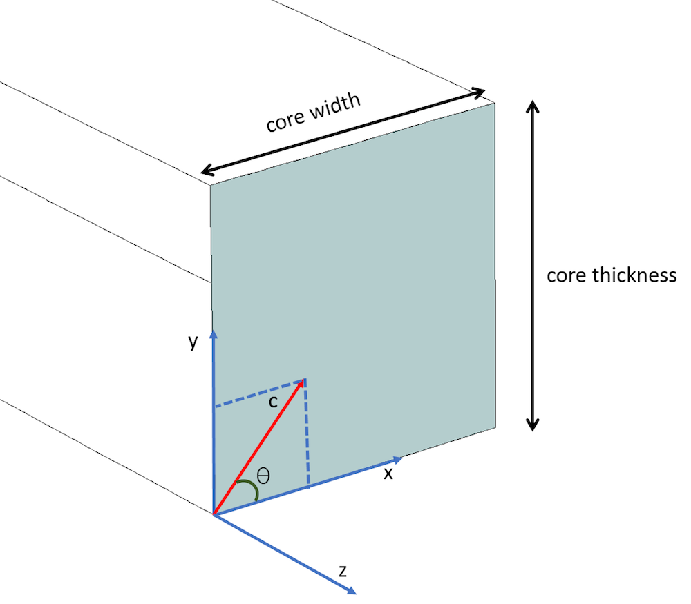
The c-axis lying in the XY plane and making an angle of \theta with the x-axis.
\begin{bmatrix}
cos(\theta) & -sin(\theta) & 0 \\
sin(\theta) & cos(\theta) & 0\\
0 & 0 & 1\\
\end{bmatrix}
\begin{bmatrix}
\epsilon_{xx} & 0 & 0 \\
0 & \epsilon_{yy} & 0 \\
0 & 0 & \epsilon_{zz} \\
\end{bmatrix}
\begin{bmatrix}
cos(\theta) & sin(\theta) & 0 \\
-sin(\theta) & cos(\theta) & 0\\
0 & 0 & 1\\
\end{bmatrix}
\begin{bmatrix}
(\epsilon_{xx}) cos^2(\theta) + (\epsilon_{yy}) sin^2(\theta) & (\epsilon_{xx}) sin(\theta) cos(\theta)-(\epsilon_{yy}) sin(\theta) cos(\theta) & 0 \\
(\epsilon_{xx}) sin(\theta)cos(\theta)-(\epsilon_{yy})sin(\theta)cos(\theta) & (\epsilon_{yy}) cos^2(\theta) + (\epsilon_{xx}) sin^2(\theta) & 0\\
0 & 0 & \epsilon_{zz}\\
\end{bmatrix}
The relative permittivity tensor ε is treated along with a rotation matrix, rotating the c-axis in the XY plane with angle \theta.
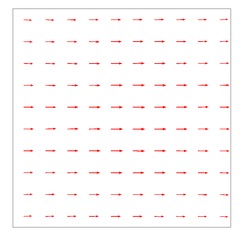
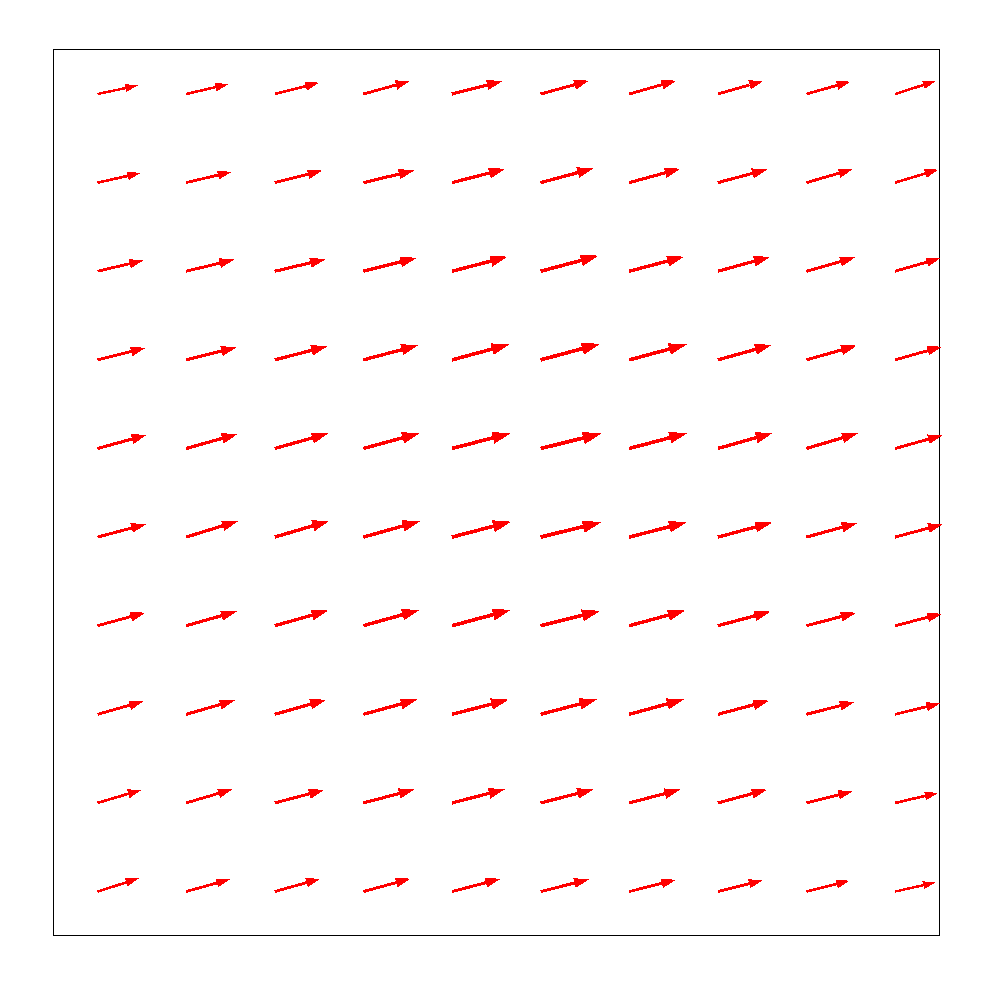
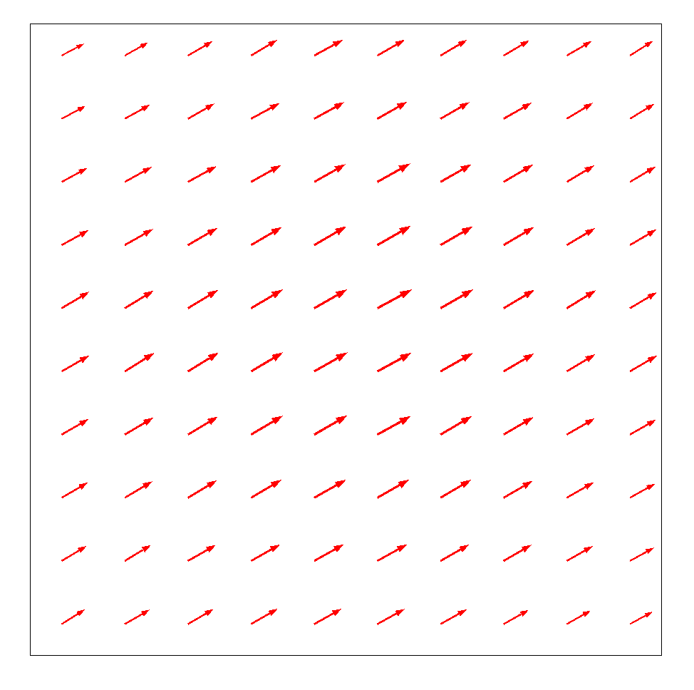
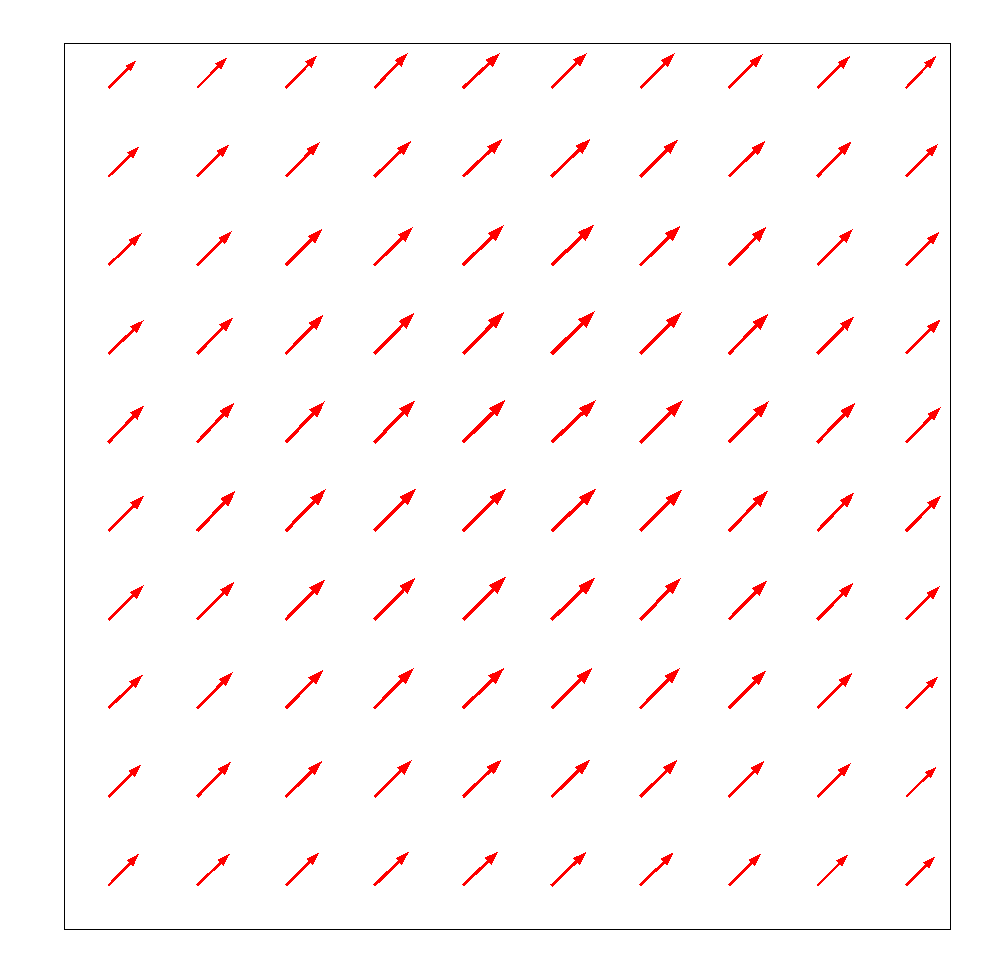
Finally, the modal analysis of the waveguide with off-diagonal anisotropic core and isotropic cladding, where the optic axis makes angles of 0, 15, 30, and 45 degrees with respect to the principal x-axis, as shown below. Here, it could be observed that the direction of the in-plane magnetic field changes according to the change in the angle of the optic axis. The dispersion curve could also be plotted by parametrically sweeping the length of the core and cladding from 0.5 um to 4 um, while considering the angle \theta as 45°. The dispersion curve tends to be similar to the dispersion curve of the diagonal anisotropy, as discussed above.
Mode analysis, including off-diagonal terms, for θ = 0° (top-left), θ = 15° (top-right), θ = 30° (bottom-left), and θ = 45° (bottom-right). The figure represents the magnetic field lines within the core for different rotation angles.
Off-Diagonal Longitudinal Anisotropy (YZ Plane)
Finally, when considering the longitudinal anisotropy where the optic axis (i.e., c-axis) lies in the YZ plane and makes an angle of \phi with the y-axis, the diagonal components \epsilonxx, \epsilonyy, \epsilonzz and the off-diagonal components \epsilonyz and \epsilonzy are nonzero, while the rest of the components are zero. The relative permittivity tensor could be evaluated by using the rotation matrix [R] as shown below, where the rotation matrix [R] is specifically for rotating the c-axis in the YZ plane. \epsilonyy is the square of the extraordinary refractive index (~2.19), because the c-axis lies along the principal y-axis, while \epsilonxx, \epsilonzz is the square of the ordinary refractive index (~2.31). The off-diagonal elements \epsilonyz and \epsilonzy are derived from the multiplication of the matrices as stated below.
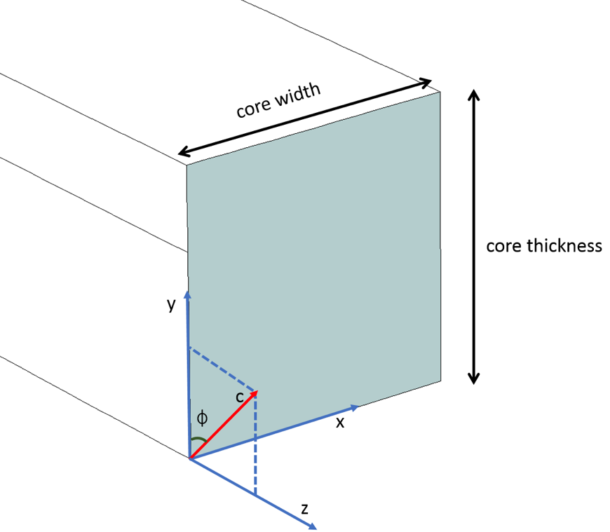
The c-axis lying in the YZ plane and making an angle of \phi with the x-axis.
\begin{bmatrix}
1 & 0 & 0 \\
0 & cos(\phi) & -sin(\phi)\\
0 & sin(\phi) & cos(\phi) \\
\end{bmatrix}
\begin{bmatrix}
\epsilon_{xx} & 0 & 0 \\
0 & \epsilon_{yy} & 0 \\
0 & 0 & \epsilon_{zz} \\
\end{bmatrix}
\begin{bmatrix}
1 & 0 & 0 \\
0 & cos(\phi) & sin(\phi)\\
0 & -sin(\phi) & cos(\phi) \\
\end{bmatrix}
\begin{bmatrix}
\epsilon_{xx} & 0 & 0 \\
0 & (\epsilon_{yy}) cos^2(\phi) + (\epsilon_{zz}) sin^2(\phi) & (\epsilon_{yy})sin(\phi)cos(\phi)-(\epsilon_{zz}) sin(\phi)cos(\phi)\\
0 & (\epsilon_{yy})sin(\phi)cos(\phi)-(\epsilon_{zz}) sin(\phi)cos(\phi) & (\epsilon_{zz}) cos^2(\phi) + (\epsilon_{yy}) sin^2(\phi)\\
\end{bmatrix}
The relative permittivity tensor ε is treated along with a rotation matrix, rotating in the YZ plane with angle \phi.
A modal analysis is then performed where the length of the waveguide is parametrically swept from 0.5 um to 4 um to derive the dispersion curve for the longitudinal anisotropic core, as shown in the figure below. In this case, \phi = 45° (i.e., the c-axis lies in the YZ plane and makes 45° with the y-axis) (Ref. 3).
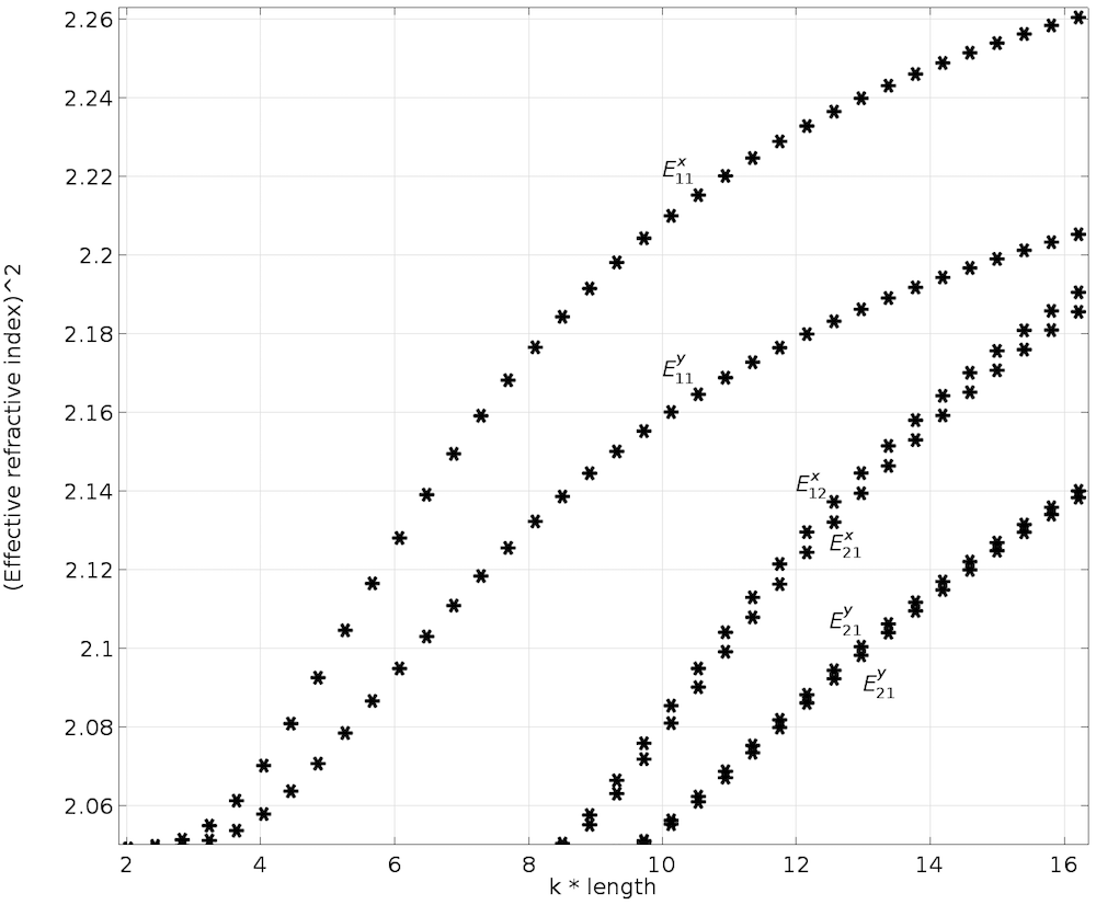
Dispersion curve with longitudinal anisotropic core.
Final Thoughts on Modeling Anisotropic Materials
In this blog post, we performed qualitative analyses (modes of propagation) and quantitative analyses (dispersion curves) of the anisotropic optical waveguide using modal analysis in COMSOL Multiphysics. Diagonal anisotropy as well as off-diagonal transverse and longitudinal anisotropy were considered to derive their dispersion relationships. These types of analyses give us more flexibility when carrying out optimization of material and geometric parameters to help us gain an in-depth and intuitive understanding of the physics of anisotropic materials.
A simple tutorial model to help you started would be the Step-Index Fiber, which involves mode analysis over a 2D cross section of the 3D optical fiber.
Next Steps
To try these models, click the button below.
Updated List of Blog Posts in the Silicon Photonics Series
References
- E. Hecht, Optics, Pearson.
- E.A.J. Marcatili, “Dielectric rectangular waveguide and directional coupler for integrated optics”, Bell Syst. Tech. J., vol. 48, pp. 2071–2102, 1969.
- M. Koshiba, K. Hayata, and M. Suzuki, “Finite-element solution of anisotropic waveguides with arbitrary tensor permittivity,” Journal of Lightwave Technology, vol. 4, no. 2, pp. 121–126, 1986.





Comments (5)
Pavel Kwiecien
June 4, 2018Unable to download the second file.
Uttam Pal
June 6, 2018 COMSOL EmployeeHi Pavel , now you should be able to download both the files. Now both the models are using relative permittivity as the constitutive relationship.
Hong Ji
June 25, 2019I have tried Step-Index Fiber model in COMSOL 4.3b and COMSOL 5.4 and got two different maximum surface electric field norm. The difference is in the order of 10^6. Do you know what’s the problem? How to fix the difference? which result is more reliable?
Hong Ji
June 26, 2019Sorry, the difference of the electric field norm results is in the order of 10^4 other than 10^6 (the result from COMSOL 4.3b is larger than that from 5.4 version. Anybody know why? Which one is right?
Uttam Pal
February 15, 2021 COMSOL EmployeeDear Hong Ji,
Suggest you to please write to support@comsol.com along with your model where you are facing the issue.