
Suppose you take a piece of metal — a thin sheet, for example — and apply some mechanical loads. The metal will deform and take on a new shape that differs from the original undeformed configuration. Say you now want to use this deformed object as part of a new geometry construction. You can then solve another physics problem on the new composite domain. Today, we’ll demonstrate how to use a deformed object as an input to a geometry sequence.
Addressing the Deformation of Objects
Solid objects change their size, shape, and orientation in response to external loads. In classical linear elasticity, this deformation is ignored in the problem formulation. As such, the equilibrium equations are formulated on the undeformed configuration. In many engineering problems, the deformations are so small that the deformed configurations are not appreciably different from the undeformed configuration. Ignoring the changing geometry therefore makes practical sense as this yields a linear problem that is easier to solve.
On the other hand, for problems like metal forming, where the deformation is large, the equilibrium equations have to include the effect of changing geometry. Updating the equilibrium equations to include the effect of changing geometry introduces a nonlinearity known as geometric nonlinearity.
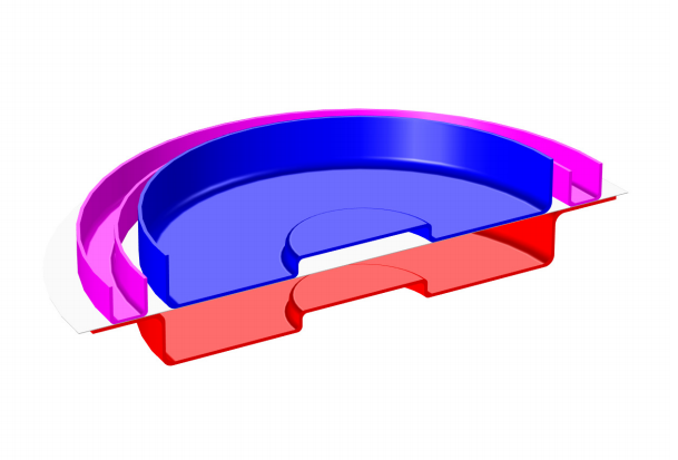
Model geometry for a sheet metal forming process, where deformations can be rather large.
When geometric nonlinearity is included in structural analysis, the COMSOL Multiphysics® software automatically makes a distinction between Material and Spatial frames. The material frame corresponds to the undeformed configuration, while the spatial frame corresponds to the deformed configuration. The software allows us to make a new geometry out of the deformed configuration; what we refer to as remeshing a deformed configuration. We can use this geometry as part of a new geometry sequence. Drill a hole in it, subtract it out of a bounding object, or simply add other geometric objects. Finally, solve a new physics problem on the composite domain. The new physics can be applied to the same COMSOL Multiphysics model in a different component, or in a different model. This is the first point that we will address.
If geometric nonlinearity is not included in structural analysis, the software does not distinguish between the material and spatial frames. Does that mean that if you do not want to include the effects of geometric nonlinearity in the equilibrium equations, you can not remesh a deformed configuration? The answer is no. You can split the two frames and force linear strains in the equilibrium equations. This is the second item that we will address.
For three-dimensional problems, there is an additional option. Surface plots can be exported as STL files. These files can be imported and used for solid modeling. In this process, we do not need to split the material and spatial frames. This is the third and last item we will discuss in today’s blog post.
Please note that remeshing a deformed configuration means simply obtaining the deformed shape computed in structural analysis. When we use this deformed geometry for a later analysis, we are not considering residual stresses. If the second analysis is another structural analysis, keep in mind that the remeshed configuration is being used as a stress-free configuration for subsequent studies.
Geometric Nonlinearity and Remeshing the Deformed Configuration
To consider effects of finite deformation in structural analysis, we have to select the Include geometric nonlinearity check box in the settings window of the study step. In some cases, COMSOL Multiphysics automatically enables geometric nonlinearity, such as when you include hyperelastic or other nonlinearly elastic materials, large-strain plastic/viscoelastic materials, or add any contact boundary conditions.
After we complete our structural analysis, we use the Remesh Deformed Configuration command to get the deformed shape. This is done in the meshing section of the Model Builder. Finally, the deformed mesh can be exported and imported back as a geometry object.
We demonstrate the above steps in the following sections.
Calculate the Deformation
Let’s consider the problem of squeezing a circular pipe between two flat stiff indenters. Because of the large deformation involved, geometric nonlinearity is included in the structural analysis, as shown in the screenshot below. Because of symmetries, we consider only a quarter of the geometry.
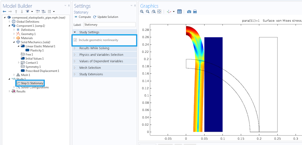
The original geometry (outline) and the deformed geometry.
Remesh the Deformed Configuration
The next step is to remesh the deformed configuration. This can be done by right-clicking on the data set (Study 1/Solution 1 in this example) and choosing Remesh Deformed Configuration. Alternatively, we can use Results > Remesh Deformed Configuration from the menu while the data set is highlighted.
In either case, this adds a new mesh to the mesh sequence and opens the Deformed Configuration settings window. Next, we click on Update. Note that for parametric or time-dependent problems, we have to pick a parameter value or time step.
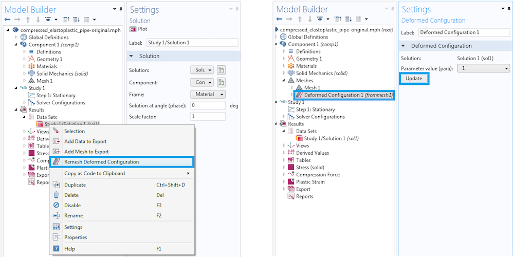
Each parameter of a parametrized data set has its own deformed configuration.
Finally, we go to the new mesh under Meshes > Deformed Configuration and build it.
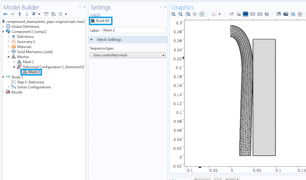
Remeshing a deformed configuration creates a new meshing sequence.
Use the Deformed Configuration in a New Geometry Sequence
One possibility is to reuse the deformed configuration in the same model file. To do so, we add another component and import the deformed mesh in the Geometry node of the new component, as highlighted in the screenshot below.
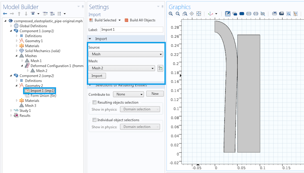
A deformed mesh from one component can be imported in the geometry sequence of another component.
We can now add more items to the geometry sequence. Let’s cut out from the bent pipe. We probably do not need the rigid indenter once we have used it to squeeze the pipe and will therefore get rid of it. The result is shown in the screenshot below. A new physics can be added to the second component.
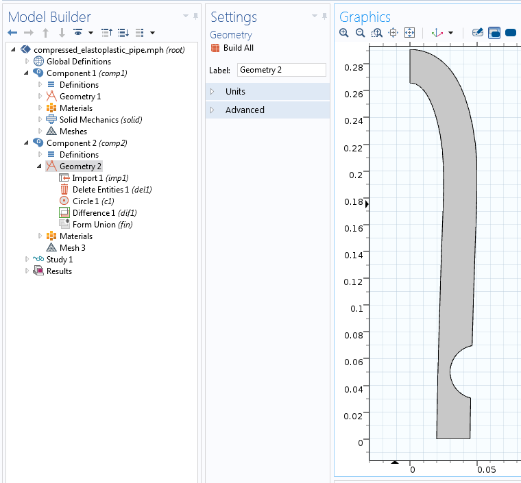
Deformed objects resulting from structural analysis can be used as part of a new geometry sequence.
To use the deformed configuration in a different model file, export it to a separate file first.
Forcing Linear Strains
If the Include geometric nonlinearity check box is unchecked, the spatial frame stays the same as the material frame. Therefore, we can not remesh the deformed configuration. If we do select the check box, COMSOL Multiphysics will include nonlinear terms in the strain tensor. What if we have a problem with infinitesimal strains and do not want to include expensive and unnecessary nonlinear strains in the equilibrium equations? The solution is to select the Include geometric nonlinearity check box in the study step, while ignoring the nonlinear strain terms by selecting the Force linear strains check box in the material model.
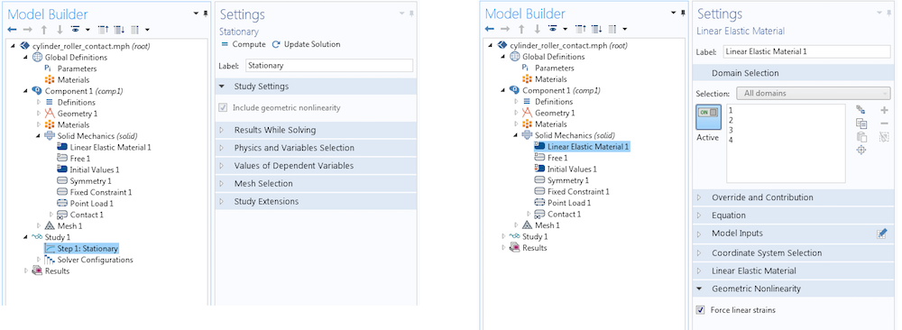
Splitting material and spatial frames while keeping only linear strains in the equilibrium equation.
The procedure for remeshing the deformed configuration remains the same as in the previous section.
STL Files and 3D Geometries
The above method, including geometric nonlinearity and remeshing the deformed configuration, can be applied to both 2D and 3D problems. In 3D cases, we have an additional option via STL files. Any 3D surface plot can be exported as an STL file. This file can then be imported in the geometry sequence of another component or model file. By adding a Deformation node to a surface plot before exporting, we can get the deformed geometry. Do not include geometric nonlinearity, unless your problem is a large deformation problem.
Export a Surface Plot with a Deformation in the STL Format

Add a deformation to a 3D surface plot and export the surface plot in the STL format.
We can edit the X-, Y-, and Z-components of the displacements in the Deformation settings window of the above screenshot to introduce anisotropic or nonuniform scaling of the displacements. In fact, these quantities do not need to be structural displacements. By typing any valid mathematical expression for deformation components, we can subject the original geometry to arbitrary transformations.
Import an STL file as a Solid Object
To use the deformed geometry in a new file or component, the STL file generated in the above step can be imported in a geometry sequence, as shown below.
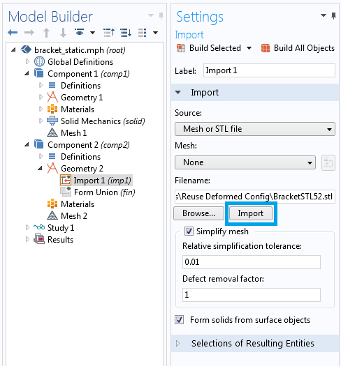
Importing an STL file to a geometry sequence.
Closing Remarks on Reusing a Deformed Shape as a Geometry Input
COMSOL Multiphysics allows seamless coupling of different physics effects. If you want to couple structural analysis with another physics on the same domain, you will find built-in tools within our software that enable you to do so. The Moving Mesh and Deformed Geometry interfaces are often used together with physics interfaces to solve problems on evolving domains.
However, if you want to use the deformed configuration from a structural analysis as part of a new geometry sequence, where you add new objects to the deformed shape or include it in Boolean operations, you can apply the strategies demonstrated above.
As always, if you have any questions, please feel free to contact us.


Comments (14)
Ivar Kjelberg
September 1, 2016Thanks for a nice and clear Blog page. One comment: I believe we can still remap the first solver stress results as “initial stress/strain” for the recessed case. With though the risk to see the part straighten back by the natural stress release effect.
Do you have any other simple way and examples to map some of the residual stress from large nonlinear deformations into a new deformed model ?
Henrik Sönnerlind
September 2, 2016 COMSOL EmployeeThanks for the comment, Ivar.
Dealing with initial stresses and strains is a topic which would be too large for this blog post (and it also is more specific to the structural mechanics community), so Temesgen chose to save that for later. We will for sure write a separate blog post on that interesting topic. Stay tuned!
Temesgen Kindo
September 2, 2016Dear Ivar,
Thank you for your nice words and suggestion.
For continuing structural analysis on a remeshed configuration, there are a couple of items that have to be handled carefully. Especially for large deformation problems. The strains will not be additive as in infinitesimal deformation. Instead you will go with multiplicative deformation gradients. Additionally when you have anisotropic materials, you want to make sure they are correctly transformed between the old and new configuration. And that is before you talk about plasticity and other history dependent problems.
To clearly explain those and other related items another blog post may be needed as my colleague Henrik suggested.
Sergey Yankin
September 2, 2016 COMSOL EmployeeFantastic blog-post!
Pablo J. Hernández
September 6, 2016Syed Faiz Ahmad
April 22, 2017Hi,
Thank you for explaining such an interseting feature.
can you please tell me how to import the stresses (generated in component1) in deformed the configuration for further analysis.
I want to model a hyperelastic square shaped film of 1mm thickness. it is streched to two times of its initial dimensions and then coupled with other physics which also requires the ‘tension’ generated while streching.
Caty Fairclough
April 24, 2017Hi Syed,
Thanks for your comment!
For questions related to your modeling, please contact our support team.
Online support center: https://www.comsol.com/support
Email: support@comsol.com
Best,
Caty
Jaap Kosse
November 17, 2017Dear Temesgen,
Concerning continuing structural analysis on a remeshed configuration, has any blog been posted on this topic? I would be very interested in it.
Caty Fairclough
December 1, 2017Hi Jaap,
Unfortunately, we do not have any blog posts on that topic. For more information, I would suggest contacting our support team.
Online Support Center: https://www.comsol.com/support
Email: support@comsol.com
Sagnik Pal
April 25, 2019Clearly written and useful blog.
晨歌 王
June 18, 2019very useful post
Montassar Akrmi
April 8, 2020Hi,
No doubt, it is a very helpful blog. But as I see in the comments, remapping the initial stress is appealing from the majority. It will be a very useful piece of work as a continuation even under very specific conditions.
Thank you,
Luis Gonzalez
November 2, 2020Thanks for the Blog page, I found it very instructive.
I believe we can remap the temperature field results to continue with a multiphysic simulation even though I’m not sure how we could do it. Could you suggest some strategies or maybe confirm this hypothesis?
Brianne Christopher
November 2, 2020 COMSOL EmployeeHello Luis,
Thank you for your comment.
For questions related to your modeling, please contact our Support team.
Online Support Center: https://www.comsol.com/support
Email: support@comsol.com