
The quality of a computational fluid dynamics (CFD) model is often determined by the quality of the mesh used to solve the problem. A good mesh facilitates convergence, reduces memory requirements, and results in accurate solutions. It is therefore worthwhile to invest time and thought into creating the mesh when solving a CFD problem. In this blog post, we describe the factors of a quality mesh and how to prepare a fluid flow model geometry for meshing.
What Constitutes a “Good” CFD Mesh?
A CFD mesh must fulfill two basic rules:
- No void regions in the computational domain
- No overlapping mesh elements
Most modern meshing tools either contain automatic checks or provide tools to easily detect and remedy transgressions. The COMSOL Multiphysics® software performs automatic checks that prevent the violation of these two rules (unless specified).
A good CFD mesh should also aim for the following three factors, which are often in conflict:
- High quality
- Sufficient resolution for the desired accuracy
- Low computational cost
Let’s go over these factors in more detail.
Mesh Element Quality
A mesh element of high quality is one that is as isotropic as possible; for example, a hexahedral cube-shaped element. Different quality measures are used to quantify the quality of elements. For instance, perfect elements commonly have quality one, but there is also the logic that perfect elements have quality zero.
COMSOL Multiphysics describes a perfect element as quality 1. A mesh element that somehow deviates from its perfect form consequently has a quality that is less than one.
The worst scenario for an element is that it collapses or inverts so that its area or volume becomes zero or negative. Such elements are generated in rare cases, and it is important to modify the mesh to eliminate them because they generate equation systems that are extremely difficult to solve and possibly have nonphysical solutions. An element with negative volume has a quality that is zero or less than zero. An example of an inverted hexahedra is shown below.
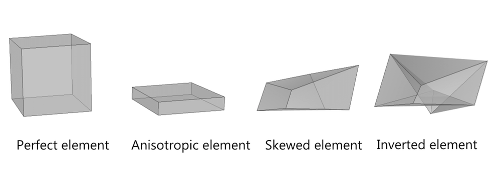
Hexahedral elements from perfect quality (far left) to inverted (far right).
A mesh element can deviate from its perfect form in a number of ways. A harmless deviation is a “compression” in one direction, as demonstrated by the anisotropic element in the figure above. The aspect ratio is defined as the length of the longest side divided by the length of the shortest side. Elements with high aspect ratios are capable of giving high accuracy for regions where the flow is anisotropic. These elements are often used to create structured meshes in general and boundary layer meshes in particular. When using high-aspect-ratio elements, though, the resulting equation system becomes harder to solve, as the aspect ratio rises. Aspect ratios up to order 100 (or close to it) are often acceptable, while aspect ratios that approach 1000 can prove troublesome.
The worst way to deform a mesh element without inverting it is to skew it. A skewed mesh element has angles that deviate substantially from 90°. Badly skewed elements have a negative impact on both the local accuracy and the condition number of the equation system (the equations are harder to solve). Skewed elements typically appear when creating boundary layer meshes or mapped meshes in curved geometries, or when transitioning from high-aspect-ratio elements to isotropic tetrahedral elements through pyramid elements. Skewness is a measure to detect skewed elements. There is no sharp lower limit on quality based on skewness, but qualities lower than 0.01 should be avoided.
A mesh quality measure that is specific to CFD is growth rate. The growth rate is the change in element size from one element to one of its neighbors, and it should be small in order to get accurate results. The highest growth rates typically appear in transitions between structured meshes, such as boundary layer meshes, mapped meshes, and free unstructured tetrahedral meshes. There is no formal upper limit for the growth rate, but a good rule of thumb is that it should not be above 20%.
Sufficient Resolution
For a CFD problem, the mesh harbors the shape functions that in turn represent the flow and pressure fields. Sharp gradients in any of these fields require a locally dense mesh in order to be resolved. Underresolved gradients are, in the best case, dissipated by the numerical discretization scheme, such as stabilization or upwinding. This reduces accuracy but can also result in widespread oscillations or even divergence. A skilled specialist in fluid mechanics can anticipate where sharp gradients are likely to appear and create locally finer mesh at these locations instead of refining the mesh everywhere.
Computational Cost
It is always possible to build a mesh that is very dense everywhere, but, in most cases, the resulting computational cost becomes immense. It is therefore important to only refine the mesh in regions where it is required by the flow and to provide a good transition to regions where larger elements can be used. But the flow is often anisotropic, so the most efficient approach is to utilize anisotropic structured meshes to capture gradients. As a result, a typical CFD mesh contains regions with structured meshes and regions with free, unstructured, meshes.
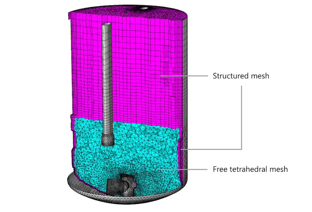
A mixer model with regions of free tetrahedral and structured meshes. Note that the boundary layer mesh along the walls is structured.
Anisotropic meshes and differences in element sizes can reduce the mesh quality, so it is not trivial to both minimize the number of mesh elements with a high mesh quality while resolving gradients in the flow.
Preparing a CFD Model Geometry for Meshing in COMSOL Multiphysics®
It is very important to properly prepare a geometry of a CFD model for meshing. Often, a CAD team provides a file containing a geometry description. The final geometry should both contain entities to prescribe appropriate physical conditions (such as boundaries to be specified as inlets and outlets) and be partitioned in a way that the mesh can be controlled. It helps to have an intuitive idea of what the solution will look like so that the mesh can be refined where necessary and coarsened where we expect that the solution accuracy allows it.
Creating the Flow Domains
Often, the geometry supplied by a CAD team is exactly what a flow mechanics specialist does not want. It is typically some solid component, such as a valve, vehicle, or electronic device, so the specialist’s first step is to remove everything that isn’t needed and create the fluid domains.
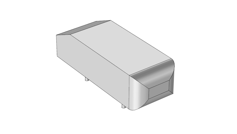
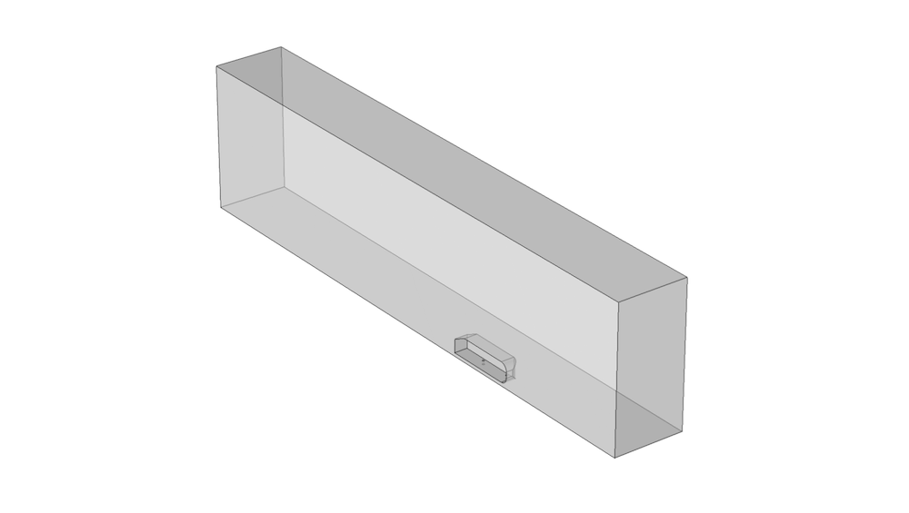
For instance, the classical Ahmed body benchmark case shows the flow around a simplified car. The CAD file that you typically see on the internet is for the actual car, but we want to simulate the flow when the car is located in a wind tunnel. So, in this case, we draw a rectangle and subtract the car to obtain a wind tunnel with the car cut out (below, right).
Notice how we have only retained half of the car. It is generally advised to utilize symmetry whenever possible, such as for symmetric flows in stationary Reynolds-averaged Navier-Stokes (RANS) simulations. (A large eddy simulation (LES), on the other hand, requires the full geometry.) In this case, using the symmetry plane removes 50% of the elements and reduces the computational time by a lot more than 50% — without any loss of accuracy!
The actual CAD geometry of the Ahmed body (left) and half of the geometry inscribed in a wind tunnel (right).
Removing Geometry Details
A CAD geometry is seldom as simple as the Ahmed body and often contains details that CFD specialists aren’t interested in, such as bolts, springs, and logotypes. These details can almost always be removed or replaced by simplified representations.
CAD geometry parts also tend not to fit perfectly. The figure below shows an impeller blade that is slightly larger than the shaft to which it is attached. If we leave these sliver faces, mesh elements need to conform with them, which results in a very dense mesh around the sliver faces. The sliver faces are typically also much smaller than the smallest allowed element size, so elements that are attached to sliver faces tend to become highly anisotropic and have high skewness. As sliver faces produce unnecessarily dense meshes with bad element quality, they should be removed.
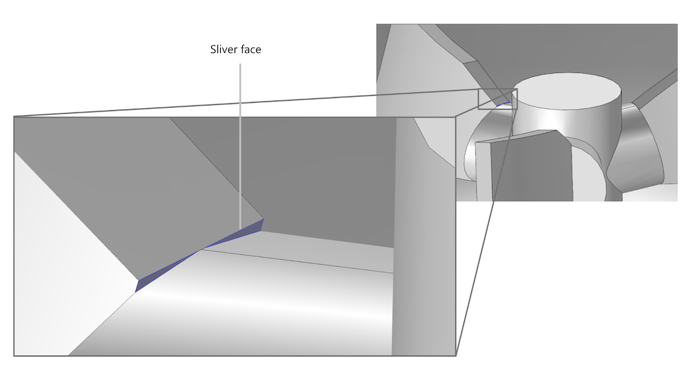
Sliver faces (in blue) on a CAD geometry of an impeller.
COMSOL Multiphysics includes tools to identify and remove small details, such as virtual operations. One important aspect when working with CFD applications is retaining the curvature of surfaces. Using virtual operations to remove edges and sliver faces may result in effectively “buckled” surface meshes, which can, in the worst case scenario, change the characteristics of the flow.
Preparing the Geometry for Mapping
Structured meshes are efficient tools to help us obtain sufficient resolution. However, not all geometries can be mapped or swept. Roughly speaking, geometries need to be homeomorph to a set of squares in 2D or a set of cubes in 3D for mapping and sweeping to work. This can require a partitioned geometry, as described in this previous blog post. In the figure below, we add a curved face that partitions the wind tunnel of the Ahmed body model in the front, where the simplified car is, and the rear, where we intend to create a structured mesh.
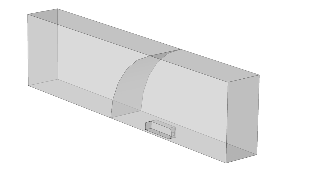
Ahmed body model geometry with a curved face that can be used to create a structured mesh in the rear part of the wind tunnel.
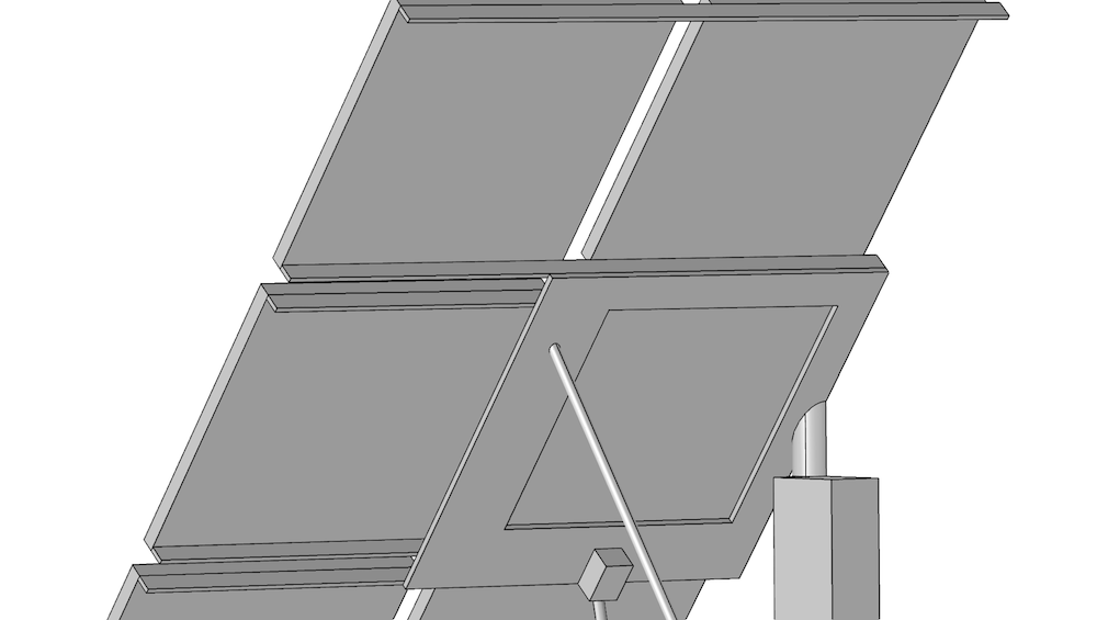
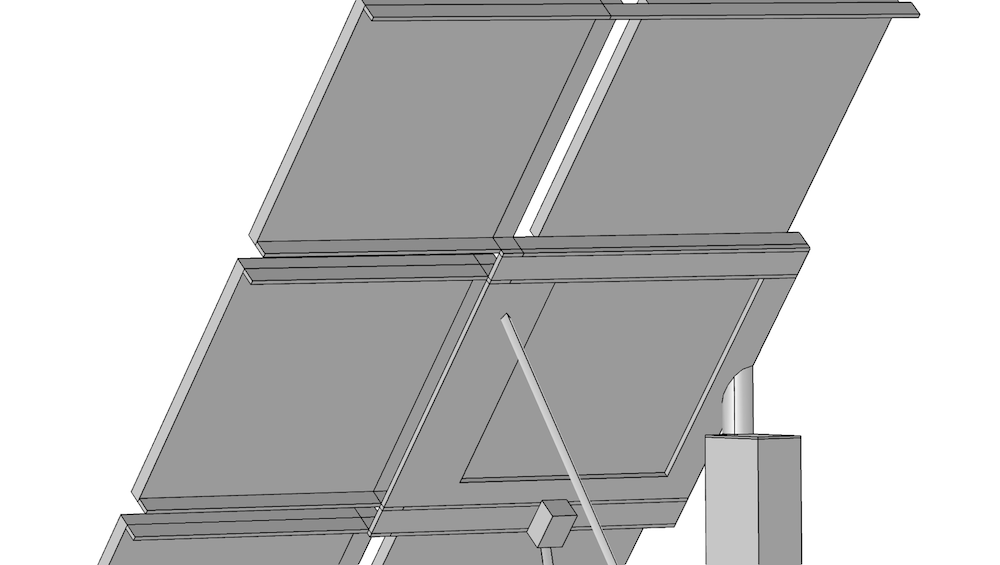
Structured meshes can be particularly useful in multiphysics simulations, such as the FSI analysis of a solar panel shown below. The solar panel consists of a lot of flat plates and beams of which the short sides must be meshed by a number of elements across. The large surfaces don’t require a fine mesh, except for the regions close to the edges. In this case, anisotropic mesh elements are required to obtain a reasonably small problem for the desired accuracy.
Structured meshes can be constructed for most of the beams and plates individually, but conflicts can arise when different meshes need to share faces or edges. Partitioning the plates and beams, as shown to the right in the figure below, remedies this issue. The additional edges and surfaces give extra control over the number of elements and their distribution.
A solar panel geometry, cleaned (left) and cleaned and partitioned (right).
Creating Mesh Control Entities
Introducing additional faces and edges to control the mesh has a drawback: The mesh needs to conform with these extra entities. This can pose a problem when boundary layer meshes are introduced. COMSOL Multiphysics uses a method where the boundary layer mesh is pushed into the domains after the volume has been meshed. The elements in the domains need to leave space for the boundary layer elements. They can move within the faces and along edges, but they cannot detach and move out of the faces or away from the edges. If elements are not allowed to move, both the elements and boundary layer elements that try to enter the domain can get squished.
The screenshot below shows a domain added behind the Ahmed body in order to control the mesh size in the wake. The domain doesn’t reach all the way to the bottom, so a boundary layer mesh introduced on the wind tunnel floor would be squished between the floor and the bottom of the extra domain if movement was not allowed. The COMSOL® software features so-called mesh control entities, as seen with the mesh control domain behind the car.
A mesh control domain disappears when it is completely embedded in a mesh, releasing the elements that were previously constrained to within its boundaries when they need to move (for example, when a boundary layer mesh is created). In this case, the boundary layer mesh on the floor below the mesh control entity will be able to move the elements above and across the mesh control faces in order to avoid squishing the elements.
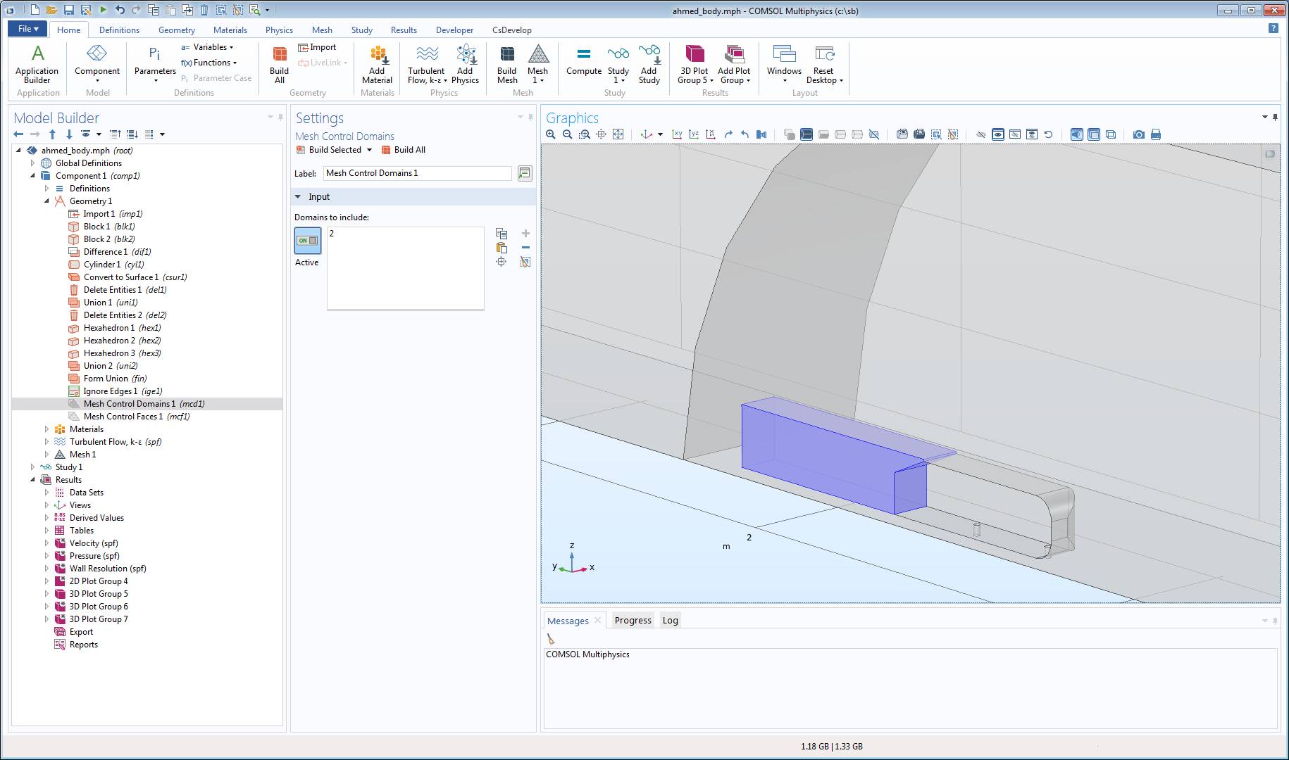
The Ahmed body model with a mesh control domain behind the simplified car.
Mesh control entities can smooth the mesh locally when the entities are removed, so they generally produce better-quality meshes locally, compared to leaving the entities in the model even if there is no boundary layer mesh.
In the next part of this blog series on meshing for CFD problems, we will go over physics-controlled mesh, the different meshing tools, and adaptive mesh refinement. Stay tuned!
Editor’s note, 6/13/18: The second part in this blog series, “Your Guide to Meshing Techniques for Efficient CFD Modeling“, is now live.
Next Steps
Check out the features and functionality that are available in the CFD Module for specialized fluid flow analyses by clicking the button below.
Further Reading
Read these related blog posts on meshing in COMSOL Multiphysics:



Comments (2)
Jhoan Guerrero
June 19, 2020Hello.
Thanks for this interesting blog.
I have a question about meshing. In order to evaluate this, there is an expression in COMSOL called qualgrowth, when you talk about growth rate quality being lower than 20%, this quantity should have a value between 0 and 0.2 or between 0 and 1.2??
Same for aspect ratio, you say that it should be lower than 100, but, there is an expression that allows to do this evaluation??? I’ve searched in that manual and read a lot of blogs but I cannot find any answer to these questions.
Thanks in advance,
Jhoan
Bjorn Bretz
December 10, 2020 COMSOL EmployeeHello,
The “Growth rate” quality measure (qualgrowth) should then be greater than 0.8. You can read about this and other quality measures in the documentation (COMSOL Multiphysics > COMSOL Multiphysics Reference Manual > Meshing > Meshing Techniques > Mesh Element Quality and Size).
There is no direct measure for evaluating the aspect ratio of an element, defined in this blog post as the length of the longest side divided by the length of the shortest side. However, the “Volume versus circumradius” measure indicates bad quality elements due to large aspect ratios.