Impedance Boundary Conditions Help in Modeling Nondestructive Testing (NDT)
How do you simplify a 3D geometry to reduce the computational resources required to model it? Do it in 2D. What if the phenomenon can only be properly simulated in 3D? Find the planes of symmetry and reduce the size, most engineering objects are symmetric in some way. What if there is no symmetry, such as the propagation of random cracks through a steel pipe? Well, as this story from COMSOL News 2012 shows, there are other methods, such as using impedance boundary conditions to simulate nondestructive testing (NDT).

Oliver Nemitz works at the Salzgitter Mannesmann Forschung (SZMF) company, which, among other R&D projects, provides and develops nondestructive testing methods for the Salzgitter Group. Salzgitter is one of the biggest steel manufacturers in Europe with over 100 subsidiaries and associated companies and revenues close to 10 billion euros. One of their divisions is tubing, where quality is assured through large magnets identifying cracks and flaws. Signals indicate “magnetic flux leakage”, and a need to act.
But what if the flaw was insignificant or within acceptable qualitative limits? Why stop the assembly line and go investigate the crack with other methods? Oliver is part of the push to utilize the existing NDT method to provide more information than just the presence of a flaw. To do this, he simulated the process and the returned signals on some standard samples with representative flaws. With this type of information, signals on the factory floor can be better analyzed to understand the extent, size and relevance of the flaw to the tubing.

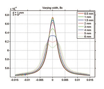
Resulting x-component of the magnetic flux density in different notch widths.
Providing a reference framework was the easy part. The modeling was difficult because flaws are not often symmetric and a full-scale 3D model of a large magnet, the large tube, and a tiny notch or crack was required. But Oliver used the built-in impedance boundary condition user interface in the AC/DC Module to model just the skin effect. Seeing as the tube’s thickness was an order of magnitude or so greater than the skin depth, this approximation was warranted. This cut the required degrees of freedom (DOFs) by a third. Read the full story in the User Story Gallery.


Comments (3)
Rajveer1957
September 17, 2012I could not find this story in COMSOL News 2012. Could you please help me to get to this article.
thanks.
Rajveer1957
September 17, 2012Sorry, I could find it now. It has changed title.
Scott Feingold
February 22, 2024 COMSOL EmployeeThis a test comment