Implementing a Simple Temperature Controller with a Component Coupling
When solving a thermal processing problem, such as the heating or cooling of a part, it is desirable to change the heating, or cooling, based upon the computed solution. That is, we may want to include a feedback loop into our model. In this article, we will set up a feedback loop using a component coupling to turn a heat load on or off depending upon the temperature of the part being heated.
Scenario: Laser Heating of a Silicon Wafer
We will look at an example in the COMSOL Multiphysics Model Library, the Laser Heating of a Silicon Wafer (you can also download it from the Model Gallery).
![]()
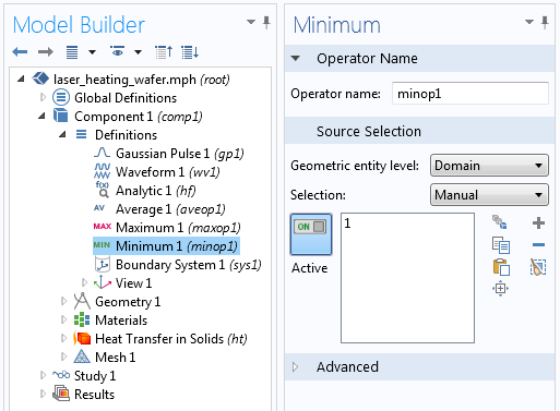
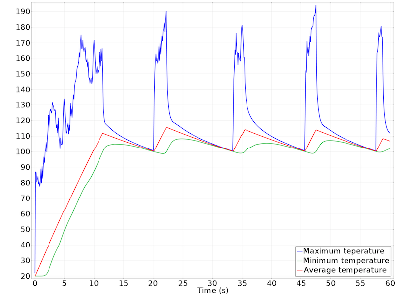
In this example, a laser heat source is modeled as a spatially distributed heat source, which is moved back and forth across the surface of the wafer, as the wafer is rotating on its stage. The source of heat is the spatially varying heat load, and the wafer is cooled via radiation to the surroundings. The model computes the temperature rise of the wafer, and uses component couplings to monitor the minimum, maximum, and average wafer temperature. The interface for these component couplings, and the results, are shown below.

Interface for Minimum Component Coupling.
![]()
Maximum, average, and minimum wafer temperature over time.
Implementing a Temperature Controller
In the existing model, the wafer is being heated continuously, but now let’s try switching the laser on or off depending upon the temperature.
We will implement a feedback control based upon the minimum temperature of the wafer. We want to continuously apply heat until the minimum temperature rises above 100°C, and then turn off the heat load. As soon as the minimum temperature drops below 100°C, we will want to turn the laser back on. This is a very simple control scheme, often called a bang-bang controller. Other control systems, such as proportional-integral-differential (PID) can be implemented in the COMSOL software, as demonstrated in this PID controller example.
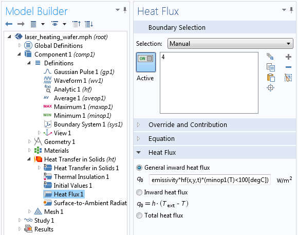
To implement the bang-bang controller, we simply use the name of the component coupling within the heat load expression. The Boolean condition, (minopt1(T) < 100[degC]), will evaluate to 1 if the condition is true, and 0 otherwise. The time-dependent solver relative tolerance is set more tightly than the default, to 1e-4, to properly resolve the switching conditions. The interface, and the results, are shown below.

The applied heat flux is turned on or off based upon a minimum wafer temperature of 100°C. emissivity*hf(x,y,t) is the term for the applied heat flux through laser heating.

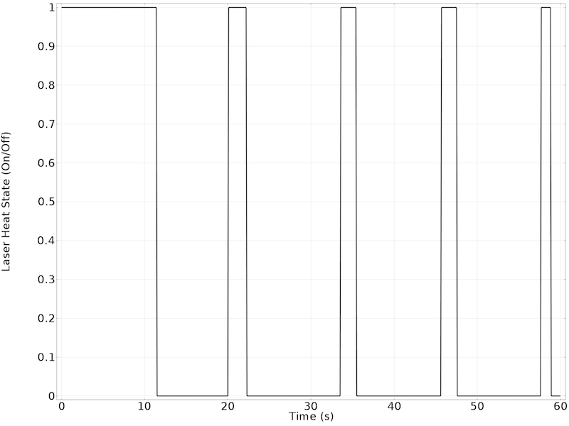
The results show the temperature control over time.

The state of the laser heat source.
Concluding Remarks
With a very simple modification to the heat source, and the usage of the Minimum Component Coupling, we have implemented a simple temperature controller in our thermal process simulation. Although we could also implement the control system with respect to the average or the maximum temperature, doing so would lead to a very fast switching of the heat source. In such situations, other more sophisticated control schemes are motivated. The advantage of the technique shown here is its simplicity of implementation.
Of course, there is a lot more that you can do with these component couplings, for example, try to combine the technique shown here with the coupling shown in my colleague Chandan’s blog post if you want to implement the controller with respect to temperature at one point on the wafer.


Comments (0)