
In a previous blog post, we discussed using field-based methods (level set and phase field) for modeling free surfaces. Another option, moving mesh, can handle free liquid surfaces that do not undergo topology changes. In this blog post, we will demonstrate how to use the moving mesh method for modeling free surfaces and compare the results with field-based methods.
A Free Liquid Surface Problem
To demonstrate the moving mesh functionality, we will use the same problem as we did in the previous blog post on the phase field and level set methods. The model is of a solid bar that is partially immersed in water in a small channel. Note that the moving mesh functionality is actually also used to prescribe the movement of the little rectangular bar back and forth on the surface in the level set and phase field methods, as well as the moving mesh method.
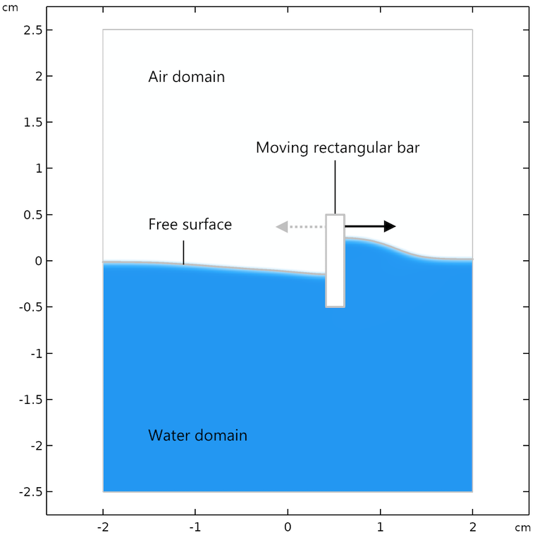
Geometry and definition of the example problem.
The moving mesh method for the free surface prescribes the displacement of the rectangular bar and keeps track of the displacement of the water surface. We account for gravity in the model by adding a source in the momentum equations. In order to compare the results from the moving mesh method with the phase field and level set methods, we use Navier slip conditions for the walls. The slip length is equal to the size of the element length.
Modeling a Free Surface with Moving Mesh
The moving mesh free surface modeling feature in the COMSOL Multiphysics® software is a completely different approach for the same problem, compared to the level set and phase field methods discussed previously. With the moving mesh approach, the free surface is modeled as a geometrical surface separating two domains. Surface tension and other surface forces are directly applied as boundary conditions at the free surface.
Using the Free-Surface feature, the displacement velocity of the free surface is obtained as the fluid’s velocity at the surface at any given time. The solution of the moving mesh equations smoothly displaces the mesh nodes inside the bulk of the fluid. The Navier-Stokes equations are in turn formulated on a moving coordinate system where the movement is obtained from the moving mesh equations that are solved simultaneously.
With this approach, the liquid is modeled while the flow field in the gas domain above the free surface is not treated other than through surface tension and pressure effects. Therefore, it is not possible to obtain the flow field in the gas phase with the current implementation. (This can, of course, be changed by manually adding a second fluid flow interface or by using the Fluid-Fluid Interface feature available in the Two-Phase Flow, Moving Mesh interface in the Microfluidics Module.) Furthermore, the moving mesh implementation in COMSOL Multiphysics is not able to treat topology changes of the free surface, such as breaking waves.
The modeling of free surfaces is, in a way, cleaner using moving mesh compared to the level set and phase field methods, since we can apply surface tension and other surface forces directly as boundary conditions, as mentioned above. Not solving for the fluid flow in the air domain above the free surface results in a substantial improvement in performance, since the number of degrees of freedom for the Navier-Stokes system are reduced to roughly half of that used by the field-based methods. Neglecting the influence of the air domain is motivated in this case by the large ratios in density and dynamic viscosity between water and air. The resulting differences are discussed in the next section.
Comparing Moving Mesh with Phase Field Results
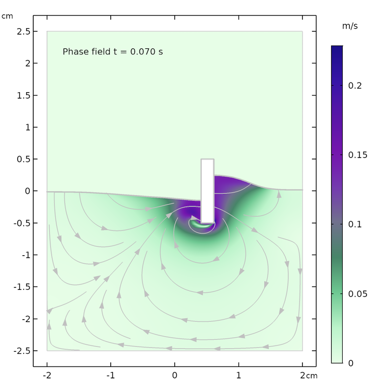
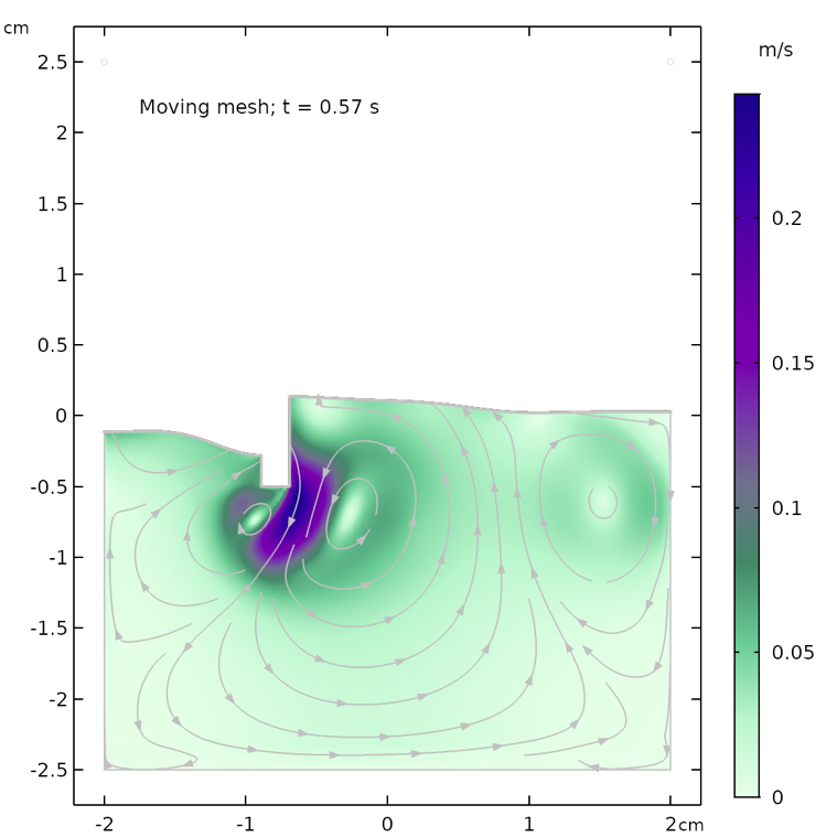
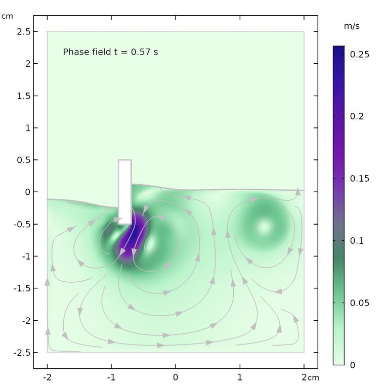
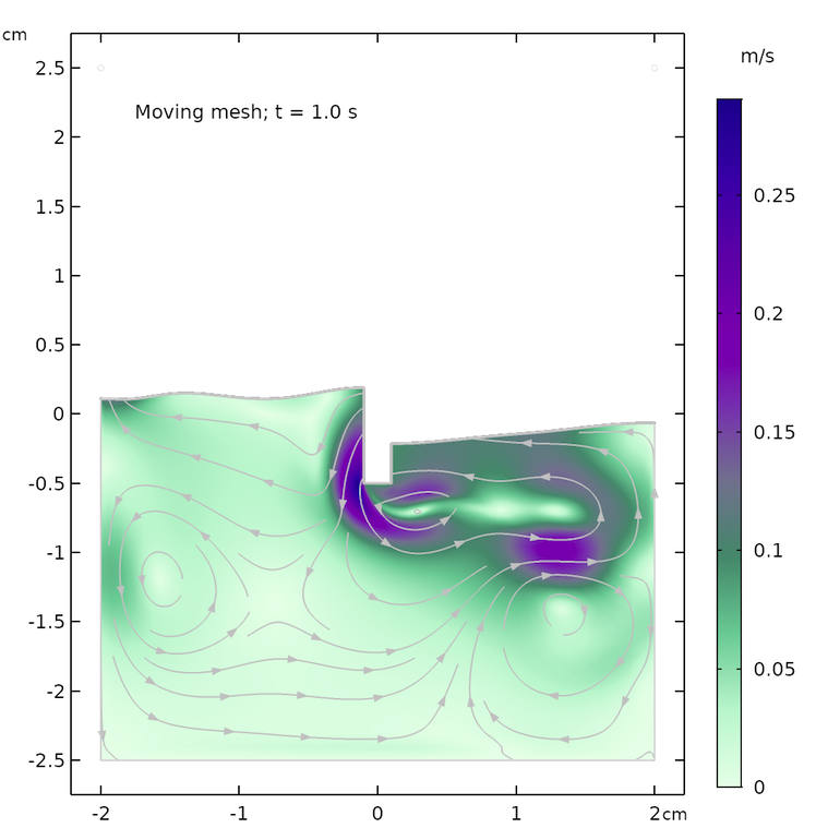
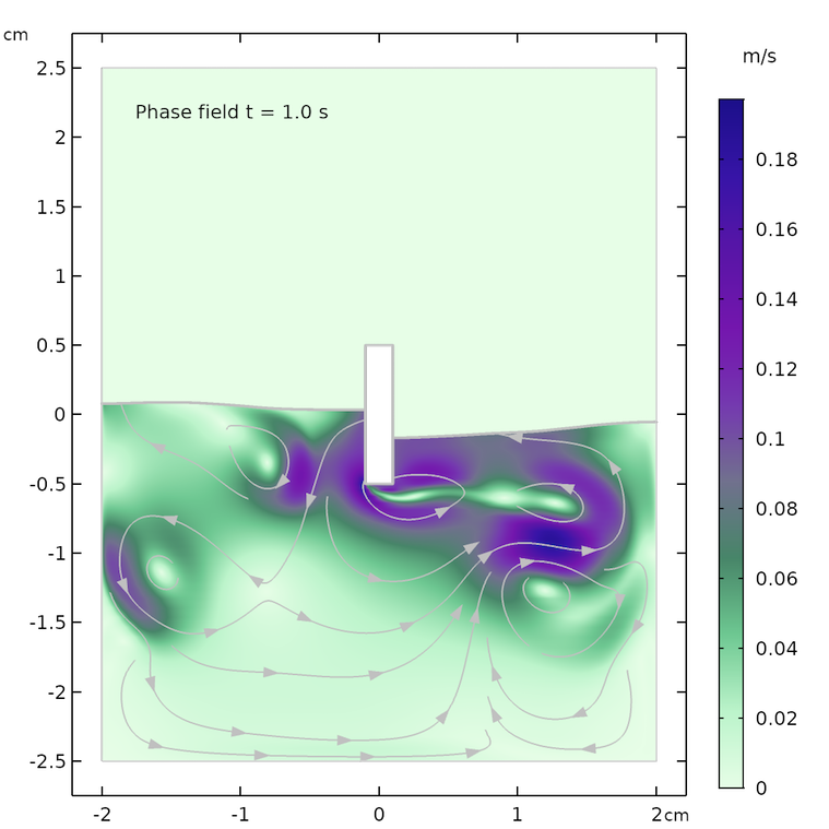
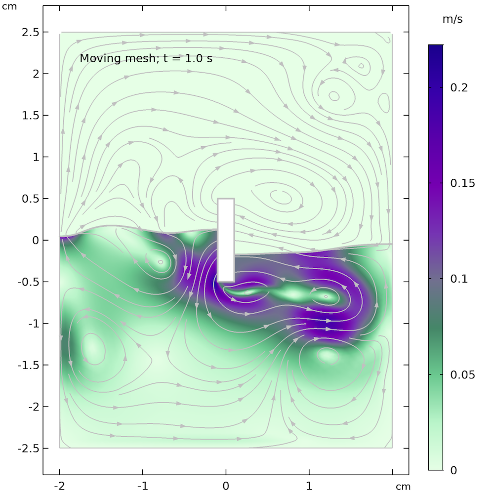
The figures below show the free surface computed using moving mesh, as compared with the results computed using the phase field method. We can see that the agreement between the two methods is decent and both the shape of the free surface and the streamlines of the velocity field are similar.
However, the models are not identical. The air domain above the free surface in the phase field case has a small damping effect on the surface in the phase field method. The air domain is not present in the moving mesh case and the surface only “sees” a constant air pressure on top of the fluid surface. In other words, the free surface in the moving mesh case does not have to displace air and can use this energy to create slightly higher waves and a more undulated surface.
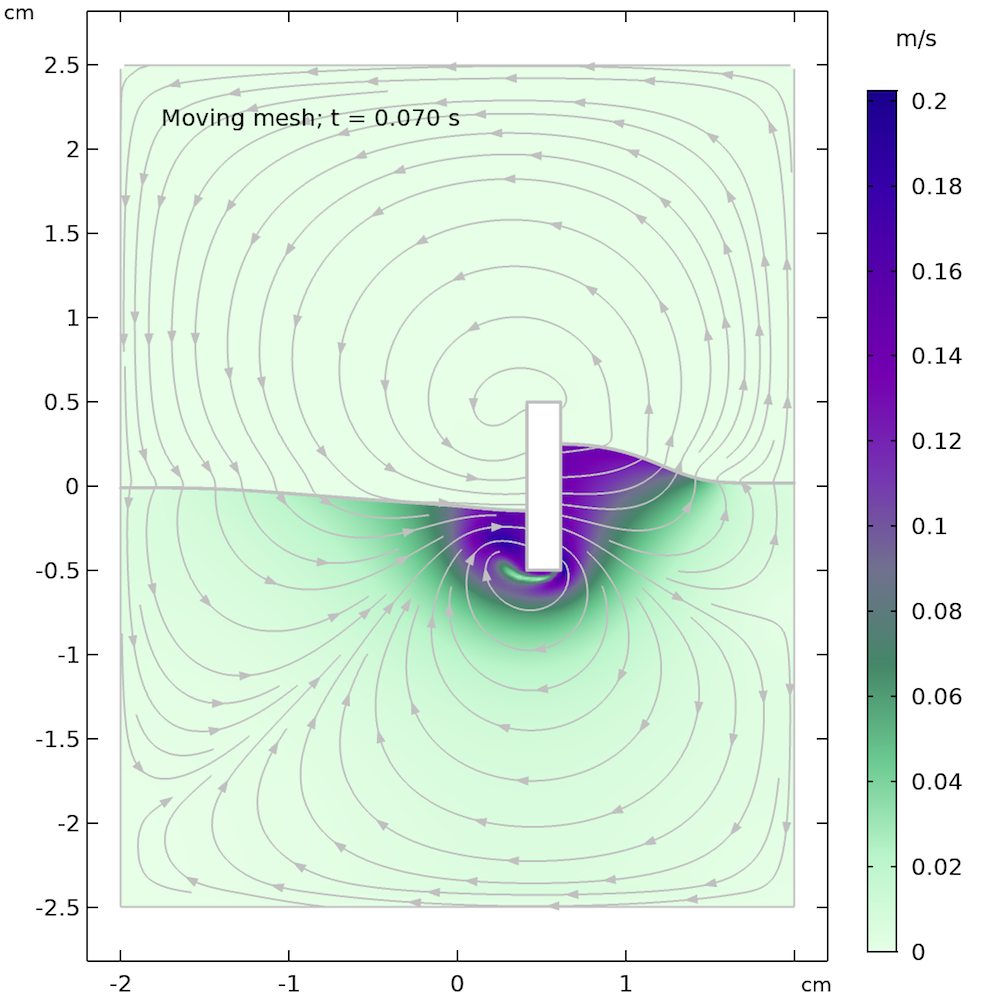
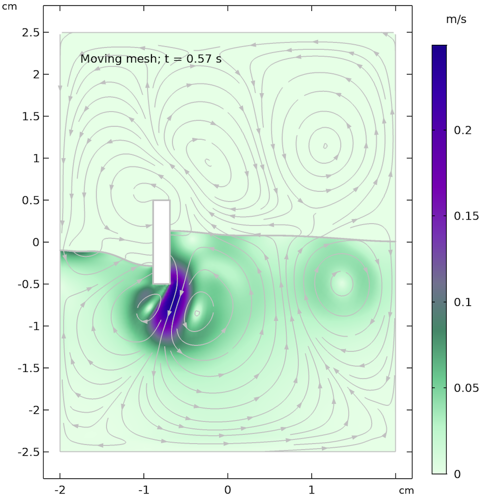
The shape of the free surface and the velocity field at different times, computed using the moving mesh interface for two-phase flow (left) and the phase field method (right).
The animation below shows the solution from the moving mesh method for free surfaces, which we can compare with our previous animation using the phase field method. We can clearly see that the free surface is more wavy and reacts more quickly compared to the phase field animation. This may be due to the missing air domain in the moving mesh, whose presence in the level set and phase field methods damps the movement of the free surface.
Animation obtained from the moving mesh method for free surfaces.
We can also compare the default free surface moving mesh feature with the full Two-Phase Flow Moving Mesh interface, which is able to account for the flow field in both the liquid and gas phases. We can see that the pattern of the flow field and the magnitude of the velocity vectors are very similar for the moving mesh with two phases compared to the results with the phase field method. The shape of the free surface is very similar for all three cases (moving mesh, phase field, and moving mesh with two phases), but here the two moving mesh cases have a more similar shape. The conclusion is that the air domain has some damping effect on the velocity field in the liquid, according to the simulation results. In addition, the difference in how the moving mesh and the phase field methods treat the wall surfaces at the phase boundary seems to be responsible for the differences (although small) in the shape of the free surface.
Results using the Two-Phase Flow Moving Mesh interface.
Automatic Remeshing and Free Surfaces
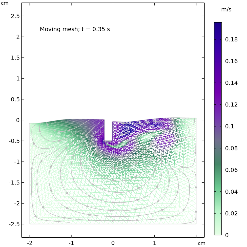
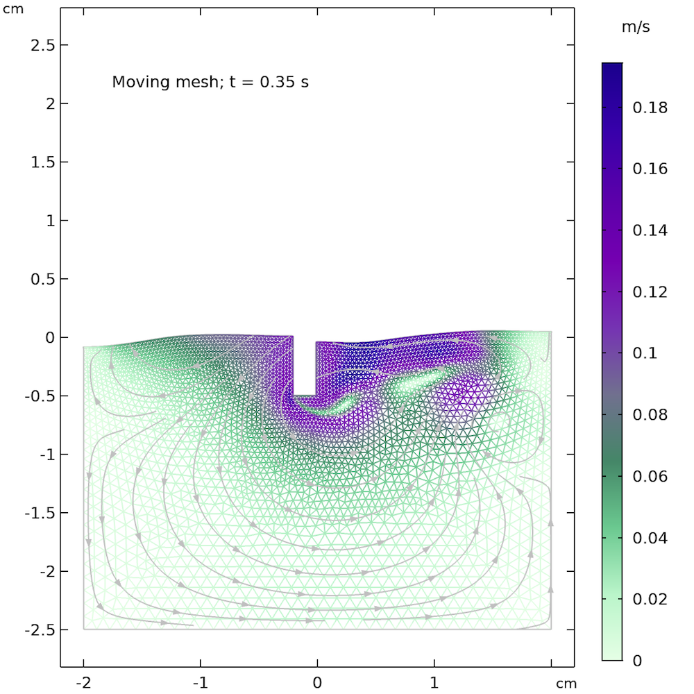
For the phase field, level set, and moving mesh methods, we can also consider using automatic remeshing, which automatically remeshes when the quality of the elements is too poor to fulfill the required quality. The quality is related to the largest angle of an element and also to the relation between the largest and smallest edges. A very large angle or a very compressed element means a poor element quality, which triggers an automatic remeshing when this functionality is selected. The figure below shows automatic remeshing applied on our little example problem. The quality of the elements after 0.35 s is poor enough to trigger a remeshing, which substantially improves the quality of the mesh.
The mesh before remeshing is triggered (left) and after remeshing (right). We can see that the elements to the right of the little rectangular bar are stretched out before remeshing, but look more isotropic after remeshing.
Fluid-Structure Interaction and Free Surfaces
In the example problem, we prescribe the displacement of the little rectangular bar on the surface. It is quite straightforward to extend the problem by applying a force to the bar and actually computing the displacement of the bar due to the counterforces applied by the fluid. This gives a so-called fluid-structure interaction (FSI) problem.
As of COMSOL Multiphysics version 5.3a, the definitions of free surface problems (or two-phase flow problems) with FSI was facilitated by the introduction of the new fluid-structure interaction interface. The figure below shows the classical problem of a fluid wall collapsing, but now also hitting a small obstacle in its way. The effects of surface tension, the position of the liquid interface, and the flow are fully coupled with the structural displacement and the stresses and strains in the little whisker hit by the flow.
Animation of two-phase flow FSI problem of a whisker that is hit by an incoming water pulse. The length scale is 5 mm in depth.
Some Conclusions From Our Example Problem
In part one of this series of blog posts, we concluded that the phase field method is superior to the level set method in terms of performance versus accuracy for modeling free surfaces for systems where surface tension effects are present. The solution of our example problem shows that the moving mesh method with the free-surface feature is even better in terms of performance versus accuracy. However, it has two shortcomings:
- It cannot handle topology changes.
- It does not by default account for the air (or other gas) above the free liquid surface.
We can conclude that the moving mesh method should be the first alternative for modeling free surfaces, provided that we do not foresee any topology changes. If we have surface tension and topology changes, then the phase field method is the best alternative. Perhaps in a future blog post, we can compare these three methods for problems with negligible surface tension effects with and without topology changes.
Additional Resources
Read the preceding blog post on the level set and phase field methods.
All of the examples above are available in the Application Gallery. If you wish, you can reproduce and check the validity of the results! Access the models mentioned in this series and read more about modeling free surfaces:




Comments (3)
SUSHIL PATEL
June 29, 2018This is really interesting. May you provide .Mph file of Modeling Free Surfaces in COMSOL Multiphysics® with Moving Mesh.
Caty Fairclough
June 29, 2018Hi Sushil,
Thanks for your comment. While the moving mesh example files are not available now, they will be added to the Application Library in a future version of COMSOL Multiphysics.
ali rahmani
July 26, 2024Hello,
I am working on a simulation setup in Comsol to simulate a 2D free-surface flow. I am using laminar flow and moving mesh physics with their corresponding boundary conditions. When I run the simulation everything works well and the results are reasonable. On another strategy, I decided to directly implement the Navier–Stokes and continuity equations instead of using the laminar flow. In this case, the results are not correct/compatible with the (laminar flow+moving mesh). After comparing the dependent variables in solver, I noticed that for (laminar flow+moving mesh) COMSOL generates one more dependent variable (comp1.spatial.lm) in comparison with (General Form PDE+moving mesh). Would you please help me how to solve this issue? it seems in the background when using (laminar flow+moving mesh) COMSOL takes a constraint?
Thank you very much,
Ali