
Thermal curing is the process of temperature-induced chemical change in a material, such as the polymerization of a thermoset resin. This process is relevant, for example, when a precursor resin is heated and hardens during the manufacturing of composites. You can often assume that the material does not flow during curing, which simplifies the analysis. Thermal curing is very easy to model within the core functionality of COMSOL Multiphysics, as we will show in this blog post.
The Thermal Curing Process
Thermosets are a class of polymer materials that undergo an irreversible chemical reaction, causing the polymer chains to cross-link and form a rigid material. This chemical reaction can be due to heat, light, or the addition of a chemical catalyst. Bakelite, one of the first thermosets, is often credited as kicking off the polymer industry. Bakelite is a very hard material that is resistant to many chemicals, is a good electrical insulator, and has an attractive surface finish. The material was used in a variety of early consumer products, such as telephones and radio cabinets.

A Bakelite radio cabinet. Image by Joe Haupt — Own work. Licensed under CC BY-SA 2.0, via Wikimedia Commons.
Bakelite and other thermosets come in various precursor forms, such as powders and thick viscous liquids. These precursors are put into a mold and heated under high pressure. Additional filler materials are often added to improve the properties of the final product. Carbon fiber and fiberglass composites, for example, bond relatively strong but flexible fibers together using a relatively rigid thermoset matrix.
Now, depending upon the exact manufacturing process, the precursor material might not move around or flow significantly during the curing step. If this is so, then you can develop a very simple model to predict the curing based upon the temperature. Let’s now look at how to implement such a model in COMSOL Multiphysics.
Modeling Thermal Curing in COMSOL Multiphysics
We will look at simulating curing during a transfer molding process, wherein the material is loaded into a mold and then heated, as shown in the schematic below. During heating and curing, the material does not move around inside the mold, and for simplicity, we won’t consider any filler materials. A thin-walled part, such as the radio cabinet shown earlier, can be reasonably modeled with a one-dimensional model through the thickness. Since the material is heated uniformly and at a known rate on both sides, we can exploit symmetry to only model one half of the material.
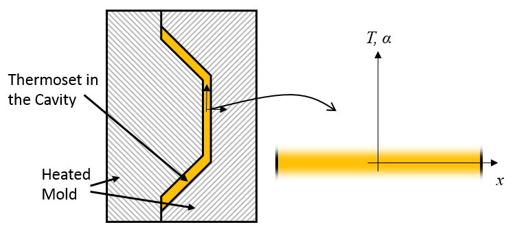
Schematic of a mold with a thermoset curing inside and the equivalent model for temperature and degree of cure.
Our model will compute the variation in time of the temperature, T, and the degree of cure, \alpha, of the thermoset from the centerline to the mold wall. Assuming no flow, the equation governing heat transfer in the thermoset precursor is:
(1)
where \rho, C_p, and k are the density, specific heat, and thermal conductivity of the material.
The degree of cure is \alpha and as the material cures, it absorbs heat, thus there is a negative volumetric heat source that is a function of H_r, the heat of the reaction. The rate of change of the degree of cure is often described by:
(2)
where the Arrhenius equation defines the temperature-dependent reaction rate, with A being the frequency factor, E_a being the activation energy, R as the universal gas constant, and n as the order of the reaction.
Let’s now look at how to set up this model in COMSOL Multiphysics, starting with the definitions of a few Global Parameters defining the properties of our representative thermoset material.
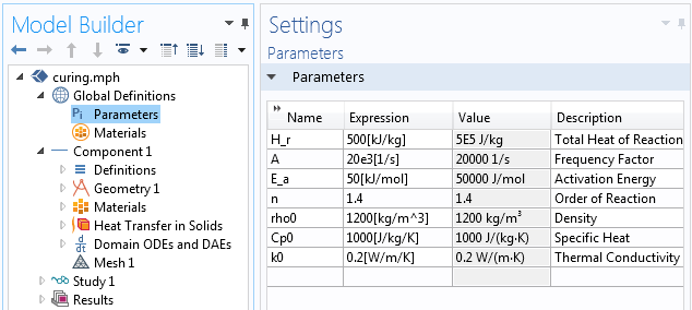
The Global Parameters define a set of representative material properties of a thermoset.
Our modeling domain is simply a 5-mm-long 1D interval, with the material properties as shown above. The Heat Transfer in Solids interface solves for the temperature distribution over time, starting with the specified initial temperature along with a Thermal Insulation boundary condition on one end. A Heat Flux boundary condition at the other end of the domain applies 10 kW/m2 due to the heating of the mold.
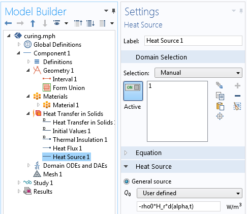
The absorption of heat due to the material curing is modeled via the Heat Source feature.
The endothermic effect of the curing is accounted for via a volumetric heat source, -rho0*H_r*d(alpha,t), as shown above. This feature implements the right-hand term from Equation 1 based upon the time derivative of the degree of cure.
We now need to add one more interface to solve for the degree of cure, and this is done via the Domain ODEs and DAEs interface, as shown below. Note that the field name is alpha. Pay special attention to how the units are set up.
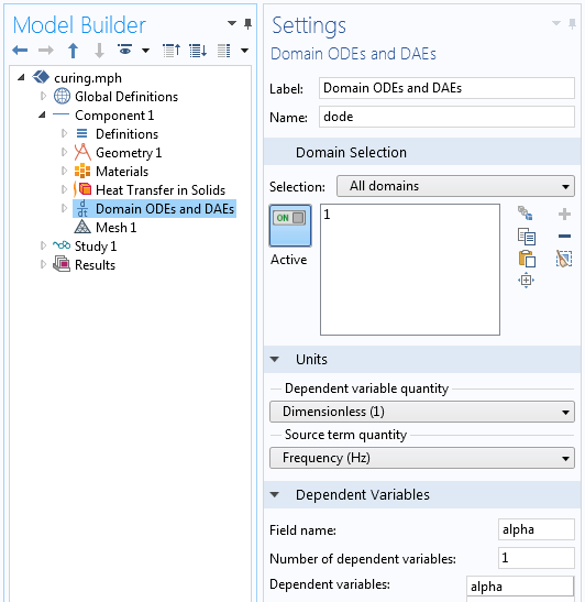
Settings for the Domain ODEs and DAEs interface, which solves for the degree of cure.
Lastly, looking at the settings for the Distributed ODE feature, we see that the Source Term is A*exp(-E_a/R_const/T)*(1-alpha)^n and the Damping term is unity, while the Mass Coefficient is zero, thus giving us Equation 2. An initial condition of zero means that the material is modeled starting from the uncured state.
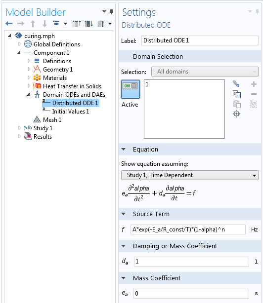
Settings for the Distributed ODE feature that solves for the degree of cure.
And that’s all there is to it: We can solve our model for a ten-minute curing time and plot the temperature and degree of cure through the thickness and at the inside and midpoint of the material, as shown below. Here, we apply a constant heat load at one side, so we will want to check the maximum temperature and the degree of cure through the thickness.
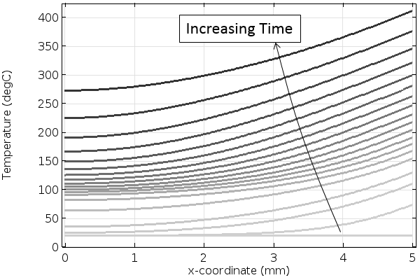
The temperature increases through the thickness of the material over time. Darker lines indicate increasing time.
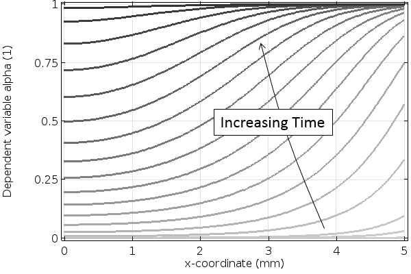
The degree of cure through the material over time. Darker lines indicate increasing time.
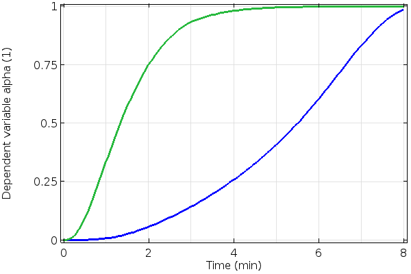
The degree of cure at the center (blue) and side (green) of the thermoset material.
Closing Remarks and Further Reading on Thermal Curing
We have shown how to quickly set up a thermal curing model entirely within the core capabilities of COMSOL Multiphysics. Of course, you can use a similar approach if you want to model the curing of other materials, such as concrete. If the material curing is due to light, such as in a photopolymerization process, you may also want to look over the various ways of modeling the interaction of light with materials, and in particular the modeling of light being absorbed within the volume of a solid as governed by the Beer-Lambert law.
The model presented here can be easily extended in many ways, including adding temperature nonlinearities to all of the materials properties, incorporating the effect of a filler material, and solving these equations in a 3D model. If you would like to see work that includes these examples, please read:
- T. Behzad and M. Sain, “Finite element modeling of polymer curing in natural fiber reinforced composites“, Composite Science and Technology, vol. 67, pp. 1666-1673, 2007.
If you have other questions or are interested in using COMSOL Multiphysics for your thermal curing modeling needs, please contact us.
Editor’s note: This blog post demonstrates how to implement thermal curing using the core functionality of COMSOL Multiphysics. As of version 5.3, the Heat Transfer Module includes an Irreversible Transformation feature that can automate this type of modeling. This blog post is maintained for those users who do not have the Heat Transfer Module and would like to implement this functionality manually.


Comments (12)
Sergey Shevtsov
March 20, 2016This problem is very close to me. Comsol is very powerful and easy tool for modeling these phenomena. It allows to successfully describe more complex tasks. See, e.g. our last work
https://www.researchgate.net/publication/295702464_Optimal_Control_Synthesis_for_Curing_the_Shell-like_Composite_Structures_in_Autoclave_Processing
I have only 3.5a license, but it allows to receive very useful results, especially, together with linked MATLAB.
Now we try to optimize a VAP infusion process. It’s complex enough, but very interesting problem.
Anas Ben Ayad
January 9, 2018Thank you, this post is useful..
I have to do something in the same way, I have done it, but I get a field of temperature and the degree of crystallziation independent of ”x” and give the same value at all points of the domain.. what can be the problem of that ?
Caty Fairclough
January 25, 2018Hi Anas,
Thanks for your comment!
For questions related to your modeling, please contact our Support team.
Online Support Center: https://www.comsol.com/support
Email: support@comsol.com
Martin Larsen
November 9, 2018First of all, thanks for your blog post we i also find quite interesting.
A couple of comments/questions though.
(A) What thoughts did you have when implementing the mould boundary condition (BC) and the time limit of 10 minute ? It seems a bit crude to assume a fixed heat flux which which go on “indefinitely” ? Your results also show temperatures around 400 degC which seem quite high ?
(B) Thermoset resins that i have seen are often said to be exothermic, thus producing heat. You explain that the resin system used in endothermic, and absorbs heat as it cures. I would recommend you to explain what type of resin system you are modelling, to avoid misunderstandings.
(C) You do not mention what NAFEMS calles Verification and Validation, which is an must-have in all modelling (https://www.nafems.org/publications/browse_buy/browse_by_topic/qa/verification_and_validation/), unless you just want to create “fancy colours”. I assume COMSOL wants to promote use of simulation in a smart way, thus i do not understand your choice of not modelling a case which can be verified and validated against literature data.
Best regards Martin Larsen
Walter Frei
November 9, 2018 COMSOL EmployeeDear Martin,
This article is meant just to present, as simply as possible, the concept of how to model temperature-dependent chemical reactions within COMSOL, hence the choice of an admittedly oversimplified set of boundary conditions and material properties. That is, the focus here is on the implementation, not any specific real-world case, with the objective of maintaining generality. If you do want to consider an exothermic process instead, switch the sign of the heat source term.
With respect to verification and validation, you may also be interested in this post:
https://www.comsol.com/blogs/verify-simulations-with-the-method-of-manufactured-solutions/
And of course we do invite our users to compare COMSOL against any published analytically verified solutions. The objective here is that, after reading this blog, you should be able to do so independently with very little effort!
Of course, if you are having any trouble with using the software, please do feel free to reach out to your COMSOL Support Team: http://www.comsol.com/support
Best Regards,
Anita Zade
February 29, 2020Thanks foe posting this blog, it is very close to my research problem.
1. May I know which version of COMSOL will support to address such problems for complex geometry?
2. Also, can we do first mold filling simulation and then thermal curing with the same module as we do for RTM process?
3. Which multi-phase model we can use for mold filling simulation?
Qasim Sahu
November 19, 2020Greeting,
Thank you for this interesting post. I have one question regarding the implementation of the domain ODE. You used the temperature field from the heat transfer module into the domain ODE. for a time-dependent problem, Does the temperature field used in the ODE interface represent the calculated temperature during the existing time step, or it represents the temperature at the previous time step? Just a simple example to illustrate my point, assuming that we are at time = 0, and we are performing the first timestep. The temperature used in the domain ODE will correspond to the initial temperature or the calculated temperature within that timestep from the heat transfer module?
Walter Frei
November 19, 2020 COMSOL EmployeeHello Qasim,
COMSOL uses implicit timestepping (https://www.comsol.com/blogs/automatic-time-step-and-order-selection-in-time-dependent-problems/) by default, so the temperature and ODE are being solved for at the same time. They are not taking on the value from the previous timestep.
Qasim Sahu
November 22, 2020Thanks for your response. That is really helpful.
Benjamin Seers
April 7, 2021Hi Walter,
Thanks for the informative post. I’m looking to extend the principals you have laid out here into a layered shell model so I can model residual stress in composite cure. One problem I am running into is that it is not possible to apply a domain distributed ODE to a layered shell. A boundary ODE will apply to the model but it calculates the DOC uniformly through the thickness which is not representative for my system. Do you have any suggestions for work arounds for this? (The irreversible transform feature mentioned in the editors note also works on a domain basis so cannot be applied to this case).
Many thanks,
Ben
Walter Frei
April 7, 2021 COMSOL EmployeeHello Ben,
Yes, what you’re describing is possible, albeit a bit challenging. You’ll need to use the Extra Dimension functionality. There are some brief examples in the documentation on this.
Harisha Bairi
April 22, 2022We can solve our model for a ten-minute curing time and plot the temperature and degree of cure through the thickness and at the inside and midpoint of the material, as shown below. Here, we apply a constant heat load at one side, so we will want to check the maximum temperature and the degree of cure through the thickness. ~~ can you please tell me how to implement this step
thank you