When a reciprocating engine’s crankshaft is under rotation, self-excited vibrations occur. These vibrations result from the eccentricity of the crank pin and balance masses on the mechanical part. Here, we’ll accurately study the response of the rotors and the orbits of the mass balances on the shaft with the Rotordynamics Module, a new add-on product to the COMSOL Multiphysics® software and Structural Mechanics Module. From these results, you can improve a crankshaft’s design to reduce vibrations, while optimizing engine performance.
Analyzing Different Components in a Reciprocating Engine
In a reciprocating engine — a power generator prominent in the automotive industry — the failure of one part can lead to the failure of the entire engine. This is an element we highlighted in a previous blog post, where we analyzed fatigue in a reciprocating engine’s connecting rods. While this approach provides a valuable way to optimize the engine’s design and improve its operational lifetime, there are many other engine parts to take into account as well.

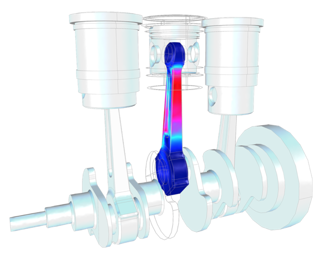
Fatigue life prediction for a three-cylinder reciprocating engine’s connecting rods.
Consider the crankshaft of the engine, for instance. This mechanical part takes the reciprocating motion of the pistons, which are connected to the crankshaft, and converts it into rotational motion. By design, the crank pins, sometimes called crank journals, are eccentric to the axis of the rotation of the shaft to enable the conversion between these two motions. But this eccentricity of the crank pin produces unbalanced forces when the crankshaft undergoes rotation. To balance such forces, some dead masses, or balance masses, are added on the crankshaft. However, due to the axial offset of the dead masses from the crank pin, an unbalanced bending moment is produced along the length of the part. The location of the balance masses is therefore selected in order to minimize this unbalanced bending moment — otherwise known as balancing the rotor.
The eccentricity of these crank pins and balance masses and the axial offset between them can cause the crankshaft to undergo self-excited vibrations when under rotation. As is the case with other machines that include rotating parts, these vibrations can impact the safety and performance of the individual part as well as the entire system that it helps power.
The new Rotordynamics Module includes functionality that enables you to perform an accurate vibration analysis of an engine’s crankshaft. Today, we’ll explore an example from our Application Gallery that showcases these features.
Model Example: Rotordynamic Analyses of a Crankshaft
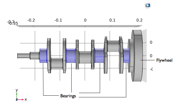
Let’s begin by looking at our model geometry. For this example, we use the crankshaft from a three-cylinder reciprocating engine. The crankshaft’s geometry is depicted in the schematic below, with both the flywheel and bearing locations highlighted.

Geometry for the engine’s crankshaft.
In the analysis, the rotor is assumed to undergo only self-excited vibrations that are caused by eccentric masses. The load on the crank pin as a result of the piston is neglected. To reduce high-frequency vibrations, material damping is applied to the rotor.
At steady state, the crankshaft’s angular speed is 3000 rpm. It is, however, ramped initially to ensure a smooth start up. The length of the ramp is selected so that the rotor completes a revolution with the linearly increasing speed from 0 to 3000 rpm and then subsequently continuing with this constant angular speed.
To accurately model the crankshaft-bearing assembly, we can use the Solid Rotor with Hydrodynamic Bearing multiphysics coupling. This coupling is comprised of the following:
- A Solid Rotor physics node
- A Hydrodynamic Bearing node
- A Solid Rotor Bearing Coupling multiphysics coupling node
To account for the thin fluid-film flow in the journal bearing, we can use the Hydrodynamic Journal Bearing feature, available in the Hydrodynamic Bearing interface.
Evaluating the Simulation Results
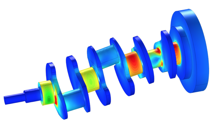
The following plot shows the stress profile for the crankshaft. As the plot indicates, the bearing close to the flywheel endures the maximum load, generating a maximum stress in the corresponding journal. The bearing close to the flywheel is also where the highest level of pressure is produced.

Stress within the crankshaft and pressure distribution on the bearing surfaces.
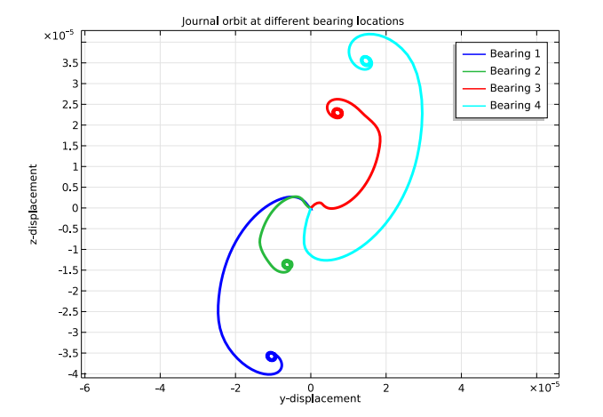
Looking at the journal orbits, we can see that they are stable for each of the four bearings. In the steady state, each journal attains their respective equilibrium positions. This is highlighted in the plot on the left below. The plot on the right, meanwhile, accounts for the lateral displacement components in the case of the third journal. The results indicate that these lateral displacements undergo damped vibration and reach an equilibrium value at steady state, as referenced above.
Left: Plot depicting the orbits of the center of the journals. Right: Plot showing the lateral displacement components for the third journal.
Learn More About the Rotordynamics Module
- For a quick introduction to the Rotordynamics Module and its various features and functionality, check out this blog post: Analyze a Variety of Rotating Machines with the Rotordynamics Module
- Watch this archived webinar to learn how to use the capabilities of the Rotordynamics Module: Analyzing Rotors and Rotating Components with the COMSOL® Software


Comments (1)
zeeshan ramzan
August 6, 2018can i do the stress analysis of two stroke 6 cylinder diesel engine crankshaft and its fatigue analysis in this module ?? how to give rotation to crankshaft and how to apply the variable cylinder loads on crankshaft as crankshaft is rotating . plz help me in my problem