
As communication systems in aviation become more complex, multiple antennas are often placed on the same airplane. This creates crosstalk, or cosite interference, which occurs between the antennas and can disturb the operation of the aircraft. The Antenna Crosstalk on an Airplane’s Fuselage tutorial model shows that you can simulate the interference between two identical antennas — one transmitting and one receiving — to analyze the crosstalk effect on an aircraft.
What Is Antenna Crosstalk?
Antennas play an important role in aviation. Pilots rely on them to ensure that their aircraft maintain safe alignment and position. This is especially important during times of reduced visibility, such as at night and in poor weather conditions. Therefore, to ensure safe flights, these antennas have to be highly reliable.
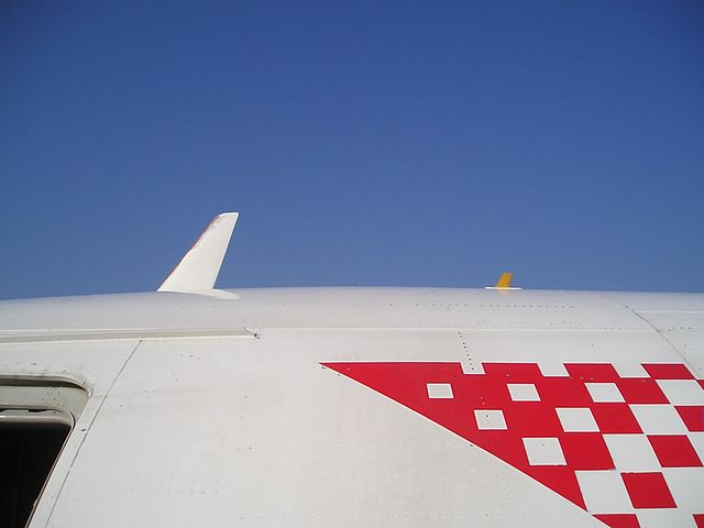
A close-up of an airplane with antennas attached to the fuselage.
Placing multiple antennas on a single airplane fuselage can be problematic, as antenna crosstalk, or cosite interference, may occur. As the name implies, this effect happens when electromagnetic signals from one antenna cross signals with another antenna and cause interference. When interference happens between a transmitting antenna that is transmitting to antennas on the ground and receiving devices that are receiving signals from antennas on the ground, it can affect the operation of the entire aircraft.
By simulating antenna crosstalk on an airplane’s fuselage, you can determine where to place the transmitting and receiving antennas to ensure safe and efficient communication. For this purpose, let’s look to the Antenna Crosstalk on an Airplane’s Fuselage tutorial model in the COMSOL Multiphysics® software.
Simulating Crosstalk on an Airplane’s Fuselage in COMSOL Multiphysics®
The airplane model is made up of a metallic body and two antennas, one on top of the fuselage and one on the bottom. You might notice that the sizes of the antenna geometries are unrealistically large. In order to provide a better view of the antenna, which is very small in reality compared to the size of an airplane, a large size was used intentionally for this introductory model. It also helps the model solve quickly for the specific purpose of crosstalk analysis. You could, of course, adapt the tutorial model so that the antennas are properly sized in reference to the airplane fuselage.
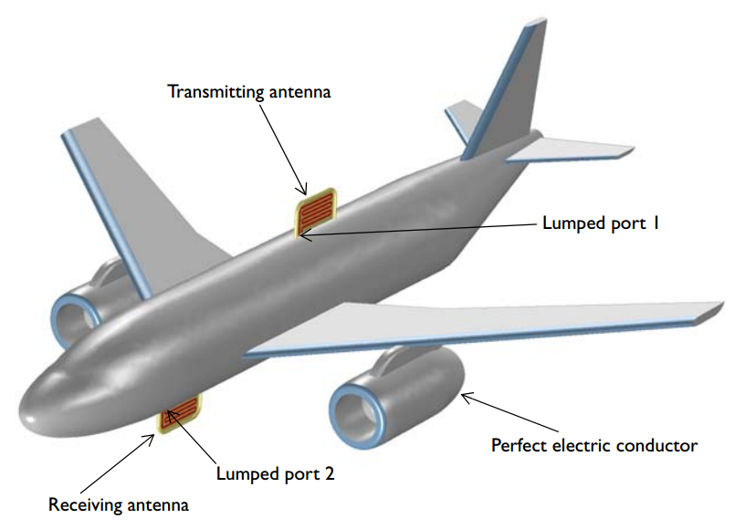
A schematic of an airplane with transmitting and receiving antennas highlighted. The size of the antennas are exaggerated.
The antennas are made up of metal strips in a dielectric block. They’re miniaturized with a meander line design, which decreases their input impedance to be lower than the reference impedance of 50 Ohm. A folded monopole antenna design technique on a large ground plane is used to match the initial low impedance.
When simulating the antennas, we also place a lumped port in the gap between the meander line and the fuselage. S-parameters are calculated from these lumped ports to show the antennas’ matching properties as well as their level of interference with each other when placed in different configurations.
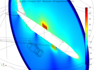
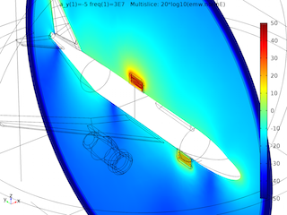
The simulation shows shadowed and lit areas of the fuselage. Shadow areas are regions where the structure of the aircraft (such as the wings, fins, and gear doors) hinder the transmitting power of the transmitting antenna. On the other hand, lit areas are not obstructed by any gear. This means that shadow areas are better suited locations to place the receiving antenna, because there will be less interference from the transmitting antenna, while lit regions are not ideal. The figures below show the electric field strength of the transmitting antenna and its effect on the receiving antenna in three different configurations.
The transmitting antenna interferes with the receiving antenna at each of the three tested locations on the bottom of the airplane.
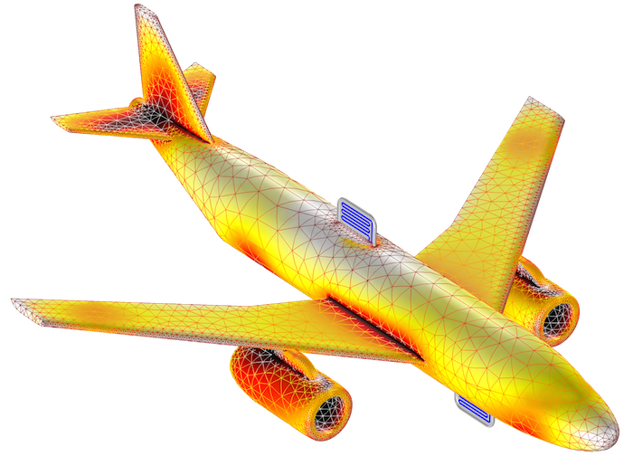
The lit and shadow areas on an airplane’s fuselage help determine the best place for the antennas as well as the level of crosstalk between them.
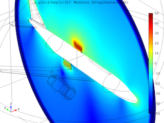
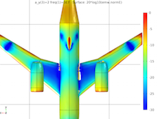
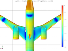
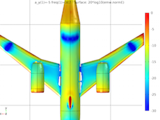
In an alternate set of figures, below, the norm of the electric field is plotted on the dB scale as the receiving antenna is tested in three different locations going from the rear to the front of the fuselage. From these images, we can deduce that the shadowing is best when the antenna is placed at the rear of the plane. This is confirmed when comparing the computed S-parameters at these three different configurations.
The shadow area of the receiving antenna when it is tested in three different locations on the bottom of the fuselage.
By modeling antenna crosstalk with COMSOL Multiphysics and the RF Module, you can optimize the antenna placement on the airplane’s fuselage for a strong overall design that ensures safe travels.
Next Step
Try it yourself: Download the tutorial model featured here by clicking the button below.



Comments (0)