
When you are creating a model, it can sometimes be difficult to keep track of all the parts in the geometry, including the conditions or constraints that apply to each section. This is especially true when dealing with large, complex geometries and multiple physics interfaces. In COMSOL Multiphysics, tools like named selections help maintain your model setup and streamline your workflow. Here’s a look at three tutorial videos demonstrating how to create and utilize Explicit, coordinate-based, Boolean, and adjacent selections.
Expedite Your Model Setup with Explicit Selections
At virtually every step of the model creation process, you need to select and apply materials, physics boundary conditions, and other settings to your model geometry. As mentioned above, overseeing the administration of these settings can be challenging, whether you are working with a simple or complicated geometry. In COMSOL Multiphysics, one tool that you can use to organize your model geometry and thus alleviate such issues are Explicit selections.
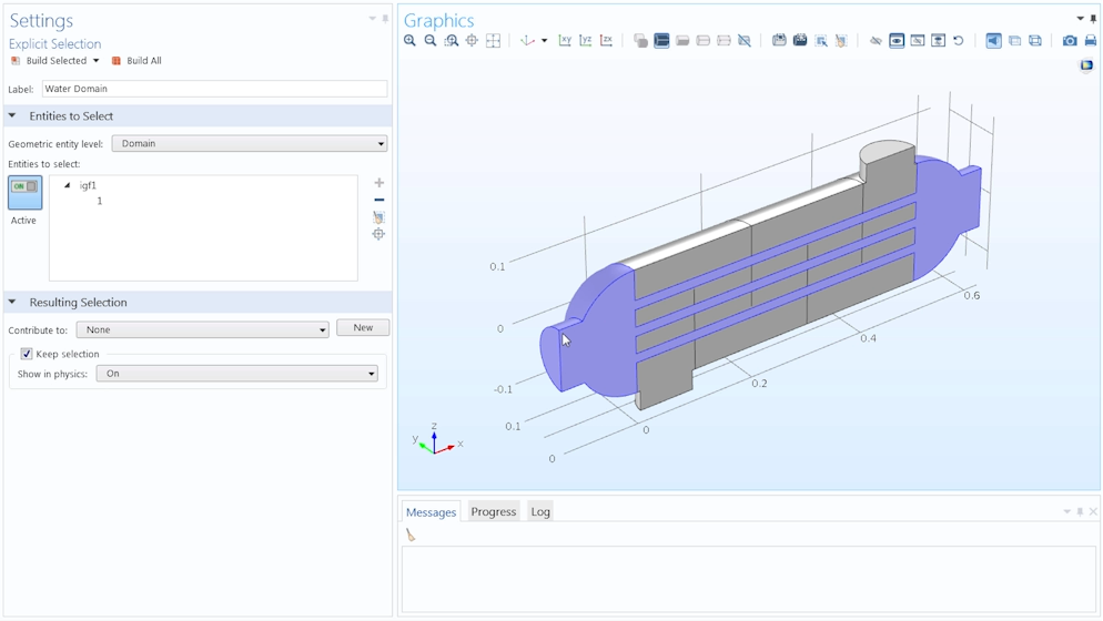
Utilizing Explicit selections to organize a model geometry.
With Explicit selections, you have the ability to create selections of individual geometric entities. Each selection can contain one or more geometric entities, with the option to rename the selection using a label that reflects the geometry it contains.
There are many advantages to this approach. Instead of referring to different parts of your model geometry by their geometric entity numbers, you can simply refer to them using the selection that displays your customized label and includes the geometric entities you assigned to it. The labeled selections are available for all physics interfaces added to the geometry. This makes it faster and easier for you to apply settings to your model. By preparing Explicit selections in advance, for any applicable node that is open in the Model Builder window, you can choose a particular selection simply by selecting its respective label from the geometry selection drop-down menu.
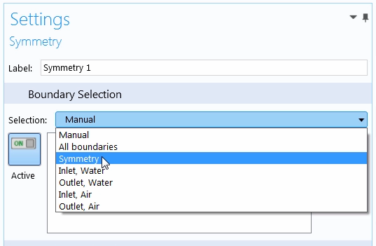
The geometry selection drop-down menu, with several different Explicit selections shown.
As an added bonus, the above approach ensures that you never accidentally omit or include any geometric entities in a selection where they do not belong. Only those entities that are included in the selections when they are originally prepared will have the settings applied to them.
Taking into account the many conveniences that correlate with using Explicit selections, we have created an eight-minute tutorial video that explains how to create and use this selection tool in your own simulation workflow. We also demonstrate how to quickly include multiple geometric entities in a selection via the Select Box and Group by continuous tangent features. The video concludes with a discussion on how Explicit selections can sometimes retain your model setup depending on how the geometry is changed, while highlighting cases where they can be utilized and their overall benefits.
Video Tutorial: How to Use Explicit Selections to Organize Your Model Setup
Coordinate-Based Selections: Modify Your Geometry Without Changing Model Settings
Besides being used to represent different parts of your model geometry, there are other selection tools available in COMSOL Multiphysics that provide additional functionality. Let’s say, for instance, that you want to run your simulation on several different versions of a geometry, with parts of the geometry removed and new parts added, while keeping all of your model settings the same. Rather than having to go back into the settings for each node in the model tree and reselect any applicable parts of the geometry, you can utilize coordinate-based selections.
Cylinder, Ball, and Box selections are just some types of coordinate-based selections that are available. Cylinder selections, for example, are used to create selections of geometric entities that are partially or completely enclosed by a cylinder.
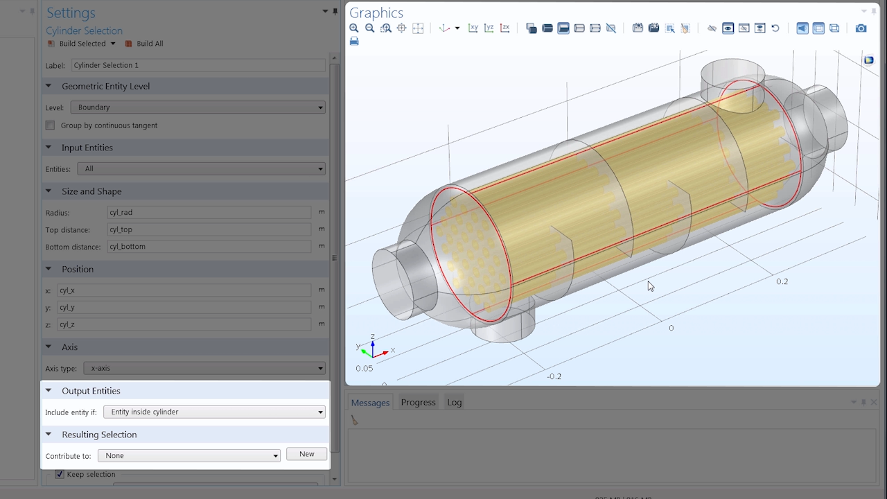
Screenshot of a cylinder selection.
Similarly, Ball and Box selections are used to create selections of geometric entities that are partially or completely enclosed by a ball or box, respectively. Unlike Explicit selections, each of these tools automatically updates if the geometry in your model changes, regardless of the means by which it changes. Whether modifications are made in the geometry sequence with the addition or removal of geometric entities or whether you’re importing a new CAD file with a significantly different design, coordinate-based selections will enable you to maintain your model setup.
In our seven-minute tutorial video on coordinate-based selections, we use two components — one containing a 3D geometry and the other a 2D cross section of that 3D geometry — to illustrate how to create each selection type. While defining these selections, we provide further details as to why we strongly encourage the use of parameters. The video also discusses the advantages of using coordinate-based selections in your model and how you can change the criteria by which geometric entities are included in your selections. To conclude, we change the geometry of the tutorial by importing a new file that exhibits a slightly different design, allowing us to see if our model assignments and definitions are maintained in spite of the introduced entity.
Video Tutorial: How to Use Coordinate-Based Selections in Your Model Setup
Create Customized Selections of Geometric Entities Using Boolean and Adjacent Selections
As mentioned earlier, each selection tool in COMSOL Multiphysics boasts different capabilities and functionalities for selecting geometric entities in your model. After learning about Explicit and coordinate-based selections, you may have already started creating a few named selections in your own simulation. But what if you are looking for a way to uniquely combine the selections you’ve already defined to create additional, even more useful selections of your model’s geometry? Boolean and adjacent selections are the ideal tools for doing so.
Boolean selections consist of Complement, Difference, Union, and Intersection selections. Each of these tools uses other previously defined selections as the input. With Complement selections, for instance, you can create selections that are the inverse of one or more selections.
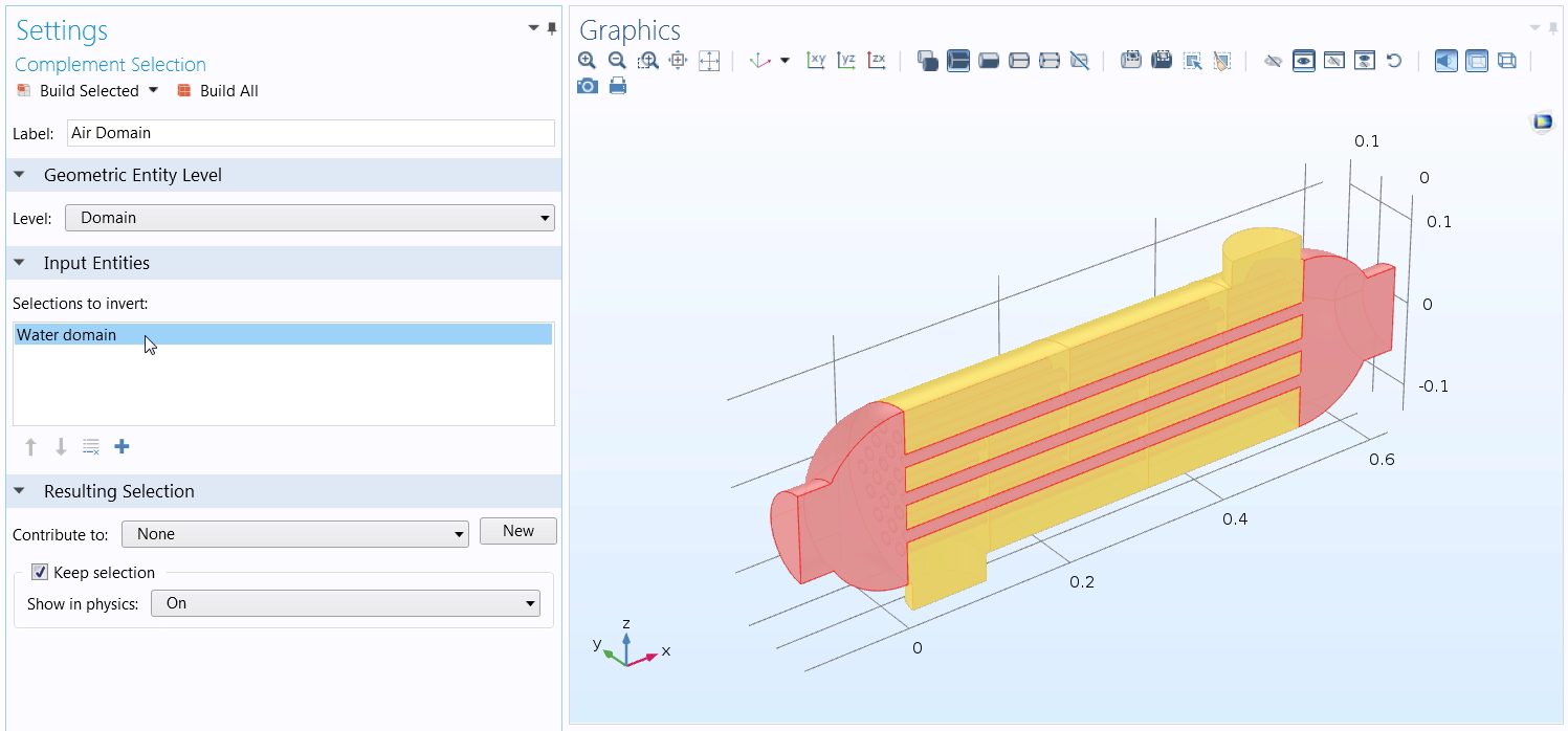
A Complement selection, with the color red representing the inverted selections.
Difference selections, meanwhile, give you the ability to create selections of entities that are included in one selection, but not another.
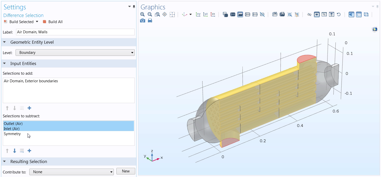
A screenshot of a Difference selection, which displays the geometric entities added and removed in the Input Entities sections.
Say you want to unite two or more selections into a single selection. With a Union selection, you can do exactly that.
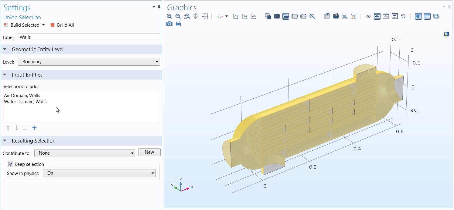
A screenshot showing a Union selection. Note that the input entities are identical to that of the Intersection selection.
Lastly, Intersection selections give you the option to create selections of any entities that are included in all of the input selections.
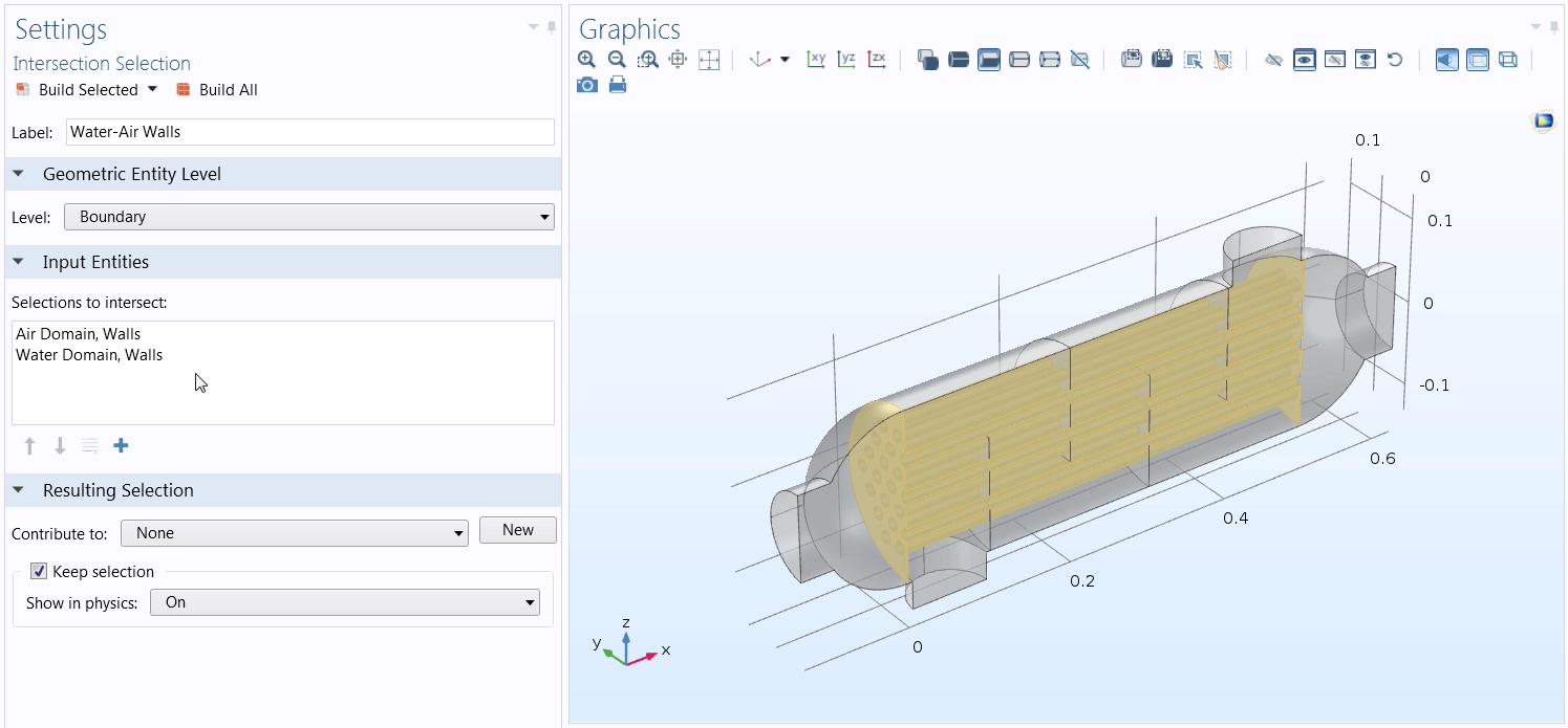
A screenshot depicting an Intersection selection. Note that the input entities are identical to that of the Union selection.
Like Boolean selections, adjacent selections also use other predefined selections as the input. This selection tool enables you to create selections of geometric entities that are touching other selections. Additional functionality allows you to choose between selecting interior or exterior geometric entities adjacent to the geometry that are included in the input selections you specify.
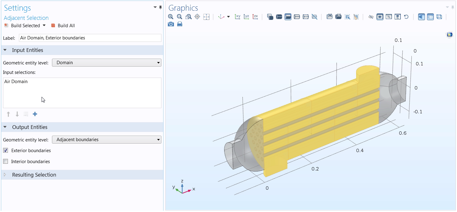
An adjacent selection, with the capability to toggle on selecting external boundaries showcased.
By utilizing Boolean and adjacent selections in your model setup with any of the other selection tools mentioned above, the possible combinations of selections to create, including the geometric entities of your choice, are infinite. This enables you to quickly and easily create unique selections of your model geometry, applying the definition that you would like. Similar to coordinate-based selections, Boolean and adjacent selections also update automatically, regardless if the changes made to the design are minor or major.
In the ten-minute tutorial video shown below, we define Boolean and adjacent selections and specify the means by which they select geometric entities. We also show you how to create each selection type, discuss their advantages in terms of the flexibility they provide, and explain why we encourage you to change the label of the selections as you define them. Near the end of the video, after assigning some definitions to a few of the selections, we change the geometry by importing a different file and then proceed to examine the changes, if any, that need to be made in order to preserve the geometry included in each of the defined selections, as well as the settings assigned to them.
Video Tutorial: Using Boolean and Adjacent Selections in COMSOL Multiphysics®
Easily Navigate Your Modeling Sequence with Named Selections
In COMSOL Multiphysics, named selections can be instrumental in simplifying your modeling processes. Such tools allow you to track the model settings applied to your geometry, retain the model settings applied to your selections if the geometry changes, and easily recognize which geometric entities are included in a selection. This not only gives you the ability to more easily navigate your model setup, but it also empowers others, such as your colleagues, to do so as well.
In the three tutorial videos featured here, you will notice that we used the same shell and tube heat exchanger tutorial model. It is our hope that by demonstrating how to create each selection type on a single model, you will not limit yourself to only utilizing any one selection tool in your own modeling processes. By combining such tools, you can optimize the overall efficiency of your simulation, achieving fast and accurate results.
Browse Additional COMSOL Multiphysics Tutorial Videos
- Interested in learning how to utilize other features and functionality available in COMSOL Multiphysics? Our Video Gallery is home to a plethora of tutorial videos. Browse these resources by simply searching under Core Functionality.


Comments (3)
Abdelmounaim Elkouissi
April 25, 2019hello thank you for this tutorial .. my questions is .. how i can create like this geometry
Amelia Halliday
April 26, 2019 COMSOL EmployeeHello Abdelmounaim, glad you found this helpful! As for creating geometry in the software, I recommend referring to the Geometry section of tutorial videos that can be found in the COMSOL Learning Center (https://www.comsol.com/learning-center).
Seiji Engelkemier
April 18, 2023Is it possible to transfer the selection definitions from a 3D component onto a 2D component when using a cross section from the 3D part?
https://www.comsol.com/forum/thread/151582/how-to-retain-selections-from-3d-domains-onto-it-s-2d-cross-section