Every year, over 40 million fire sprinkler systems are fitted worldwide. These systems are effective due to their piping designs, which are resistant to high heat and mechanical damage. A popular choice for such designs is threaded steel pipe. But analyzing a complex pipe design is challenging because of the detailed geometry. What approach can we take to efficiently combine accurate geometrical designs with reliable stress analyses? Version 5.3 of the COMSOL® software offers functionality for this purpose.
The Complex Nature of Threaded Geometries
Let’s say you just finished creating a CAD assembly of a fitting for the threaded steel pipe referenced above. Now, you want to analyze stress in your assembly in order to better understand how this portion of the pipe system performs. With our LiveLink™ interfacing products, you can perform such analyses by integrating the COMSOL Multiphysics® software into your design workflow.

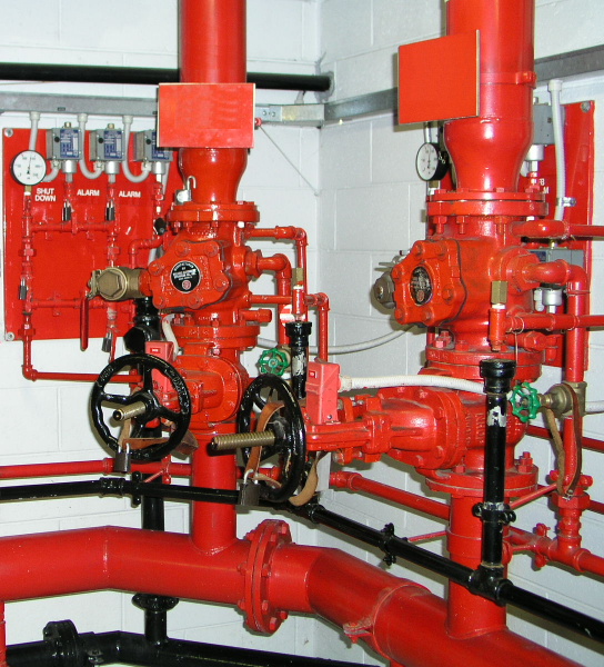
Threaded pipes are common in fire sprinkler systems. Image in the public domain, via Wikimedia Commons.
Threaded geometries include a large number of details. The complex nature of these CAD assemblies causes additional preprocessing work and takes up more computing resources during analysis. One solution is to assume that the thread is symmetric and compute the solution in a 2D section cut from the 3D object.
In previous versions of the COMSOL® software, selections from the original geometry had to be manually redefined after synchronization — a process that can be time consuming. Thanks to improvements in version 5.3, setting up CAD assembly selections is now a more efficient process. All of the relevant selections are automatically loaded and properly assigned in the COMSOL Multiphysics environment. This makes it possible to run parametric studies as well as improve 3D designs from 2D analyses.
Want to see a firsthand example? Good news: There’s a new tutorial model in the Application Gallery that highlights this functionality.
Note: While today’s example uses LiveLink™ for SOLIDWORKS®, this functionality is also available for LiveLink™ for Inventor®. For more details, see the 5.3 Release Highlights page.
Performing a Reduced Stress Analysis of a Threaded Pipe Fitting
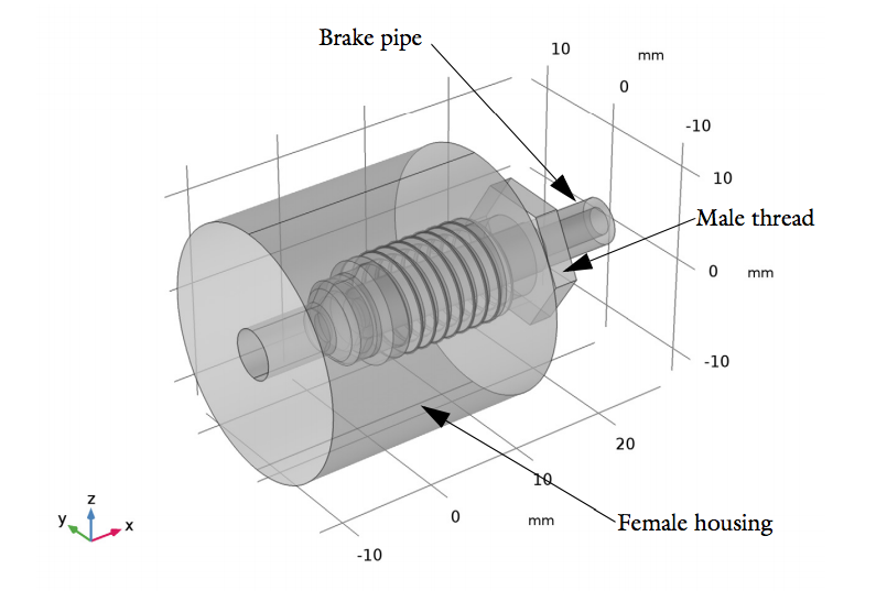
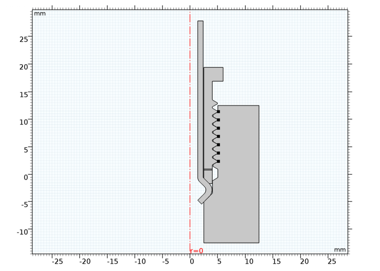
In this example, you can synchronize a full threaded pipe fitting geometry built in SOLIDWORKS® software into the COMSOL Desktop® environment via LiveLink™ for SOLIDWORKS®. To compute a reduced stress analysis, you obtain a 2D section from the 3D geometry via the Cross Section node. The analysis assumes that a torque of 5000 Nm is applied to the male thread part (shown below). This part is made up of the same steel material as the other parts in the design.
Left: Full 3D assembly synchronized in COMSOL Multiphysics. Right: 2D section cut for the stress analysis.
To compute the force transmission between each part of the assembly, the model uses structural contact. In SOLIDWORKS® software, these contact surfaces are defined as face selections. After synchronizing the assembly, all of the selections are automatically transferred over to the 2D axisymmetric model. This simplifies the process of setting up the contact pair, as it is no longer necessary to manually and individually select boundary entities in contact with one another. In particular, when it comes to the thread, you only need to create a selection for two surfaces in SOLIDWORKS® software instead of selecting fifteen edges in the 2D axisymmetric model.
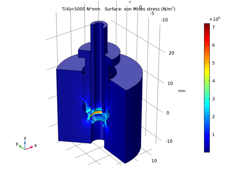
Looking at the results of our stress analysis, we can see the von Mises stress when the maximum torque (5000 Nm) is applied. The plot indicates that the maximum value of stress is less than that generally reported for using a class 10.9 alloy steel, highlighting the potential of using this material in this pipe fitting design.

Simulation plot depicting the von Mises stress with the maximum applied torque.
In version 5.3 of the COMSOL® software, you can combine your complex CAD assemblies and COMSOL Multiphysics analyses for an efficient modeling workflow.
Ready to try this tutorial yourself?
SOLIDWORKS is a registered trademark of Dassault Systèmes SolidWorks Corp.
Autodesk, the Autodesk logo, and Inventor are registered trademarks or trademarks of Autodesk, Inc., and/or its subsidiaries and/or affiliates in the USA and/or other countries.


Comments (0)