
Using the Graphics window and Graphics toolbar in the COMSOL Multiphysics® software is simple and straightforward for standard movements. Once you learn the mechanics and some more advanced techniques, you can control the camera and view angles in order to create high-quality visuals for aesthetic and informative purposes.
Editor’s note: The original version of this post was written by Lexi Carver and published on March 19, 2014. It has since been updated to reflect new postprocessing functionality.
The View Node Has Everything You Need
There are many ways to manipulate your view of the geometry directly within the Graphics window using assorted mouse clicks and movements, combined with the buttons in the Graphics toolbar. All of these view changes are reflected in the View node. There are general view and lighting options; ambient occlusion visual effects; and environment, transparency, and clipping settings.
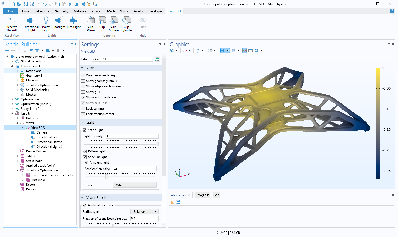
The View node is selected in the Model Builder window and some of the view settings are shown, including the Ambient Occlusion check box, which adds shading to the model. The Graphics window shows the results of a drone body topology optimization model.
Lights, Camera, Action
There are many ways to manipulate the camera to obtain more interesting and informative views. You may want to zoom into a small point of interest on a larger model while keeping the whole model in view. Or you may have a model that has a high aspect ratio. In these cases, manipulating the camera will help to show the important parts of your model.
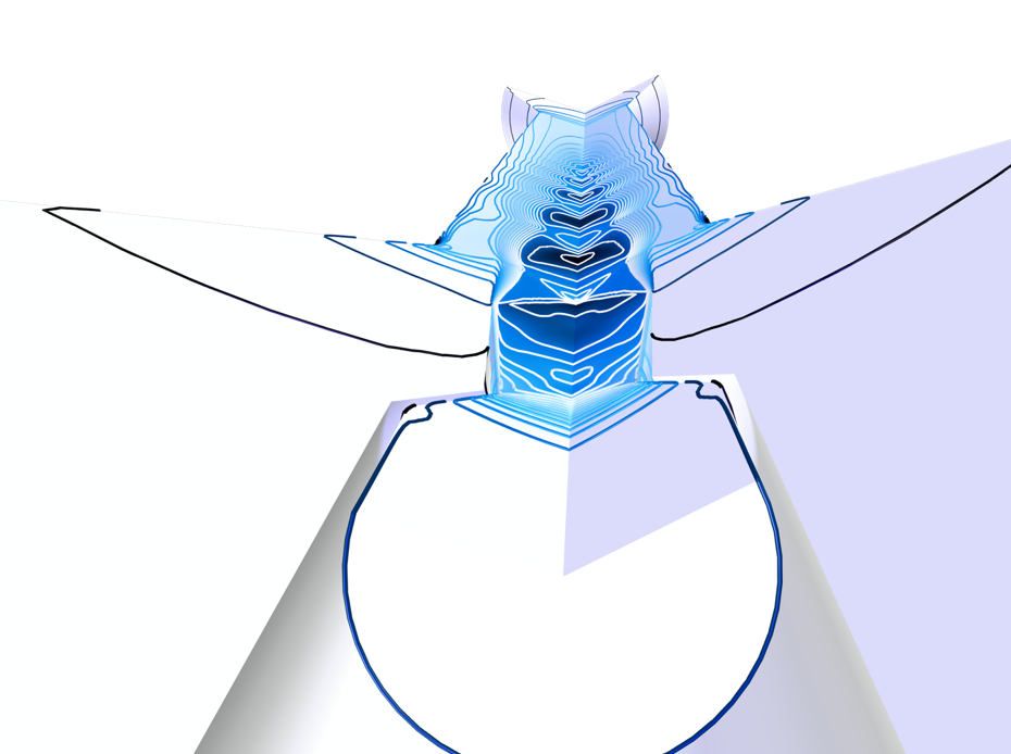
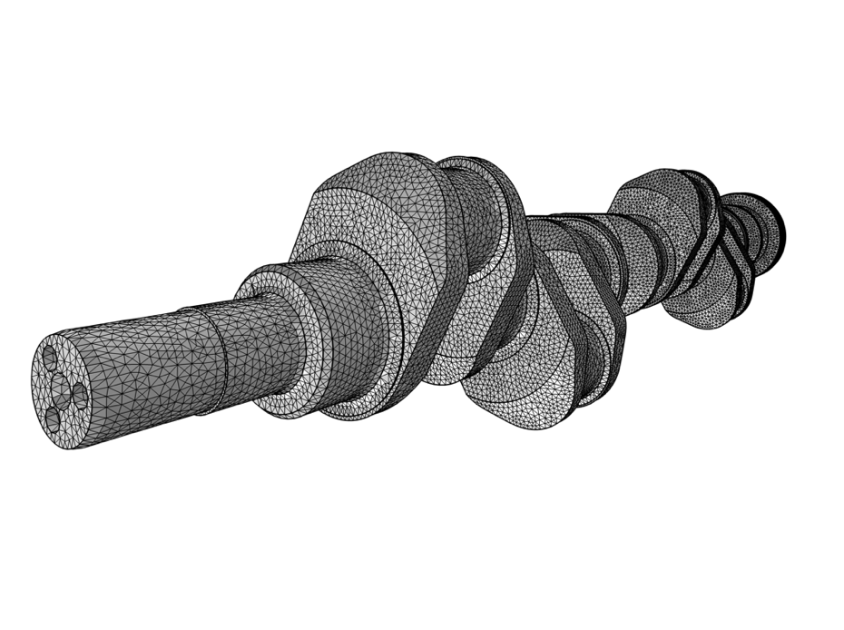
A supersonic ejector, where the inlet is a point of interest in the foreground and the outlet is visible in the background (left). The mesh of a crankshaft, with the mesh elements visible in the foreground but still encapsulating the full model (right).
Any proper photographer (amateur or professional) knows that lighting is essential for any well-developed image. When working within COMSOL Multiphysics, this is not necessarily the case; the default lighting settings are usually sufficient. However, lighting can really help to show off a model in the right scenario. Take, for instance, this Halloween-themed pumpkin model. Using various lighting features within the software, we can create the distinct yellow glow a candle produces from within a carved pumpkin.
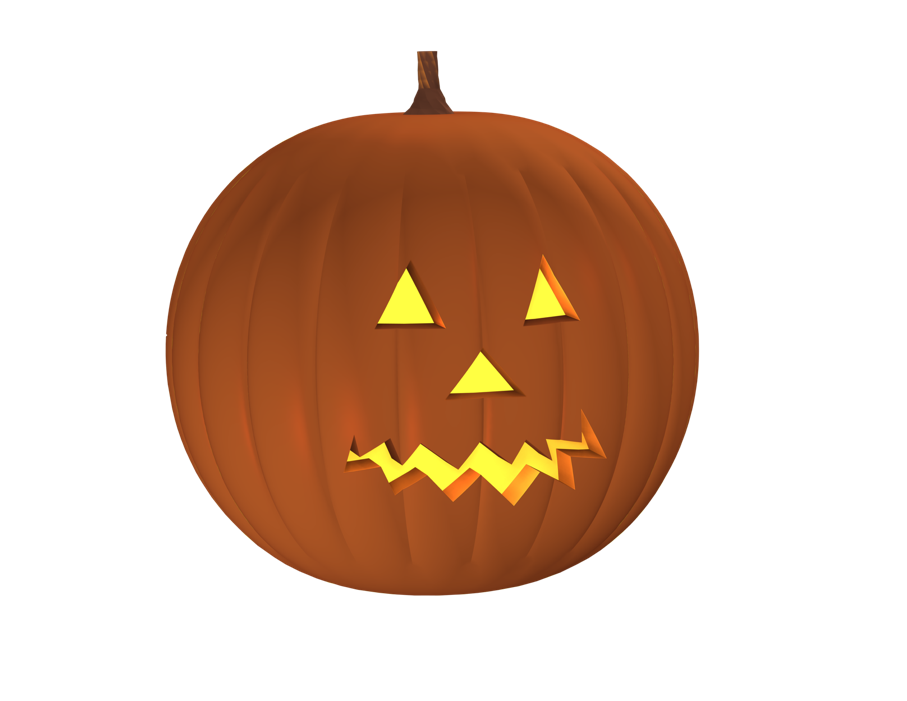
Extra yellow point lights inside the pumpkin create the yellow glow, and the Ambient Occlusion feature adds extra shadows.
Now, you might be thinking, this is all well and good, but perhaps we could see results that show actual physics. The following model employs new functionality in the Heat Transfer Module, available as of version 6.0, to simulate surface-to-surface radiation in a room heated by a stove. Heat radiates to the surrounding surfaces, and conduction spreads the heat in the furniture. Extra lighting features were used to accentuate the visualization of the radiative heat flux on the surfaces of the model. The lighting features, as well as the camera functionality, are both explained in more detail in our Learning Center article “Using the Graphics Window“.
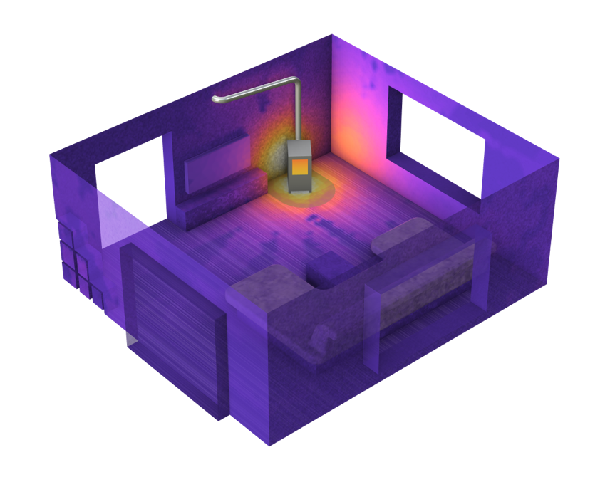
Radiative heat flux by surfaces in a room heated by a stove.
Invisibility Cloaking: Hiding Entities
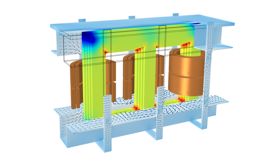
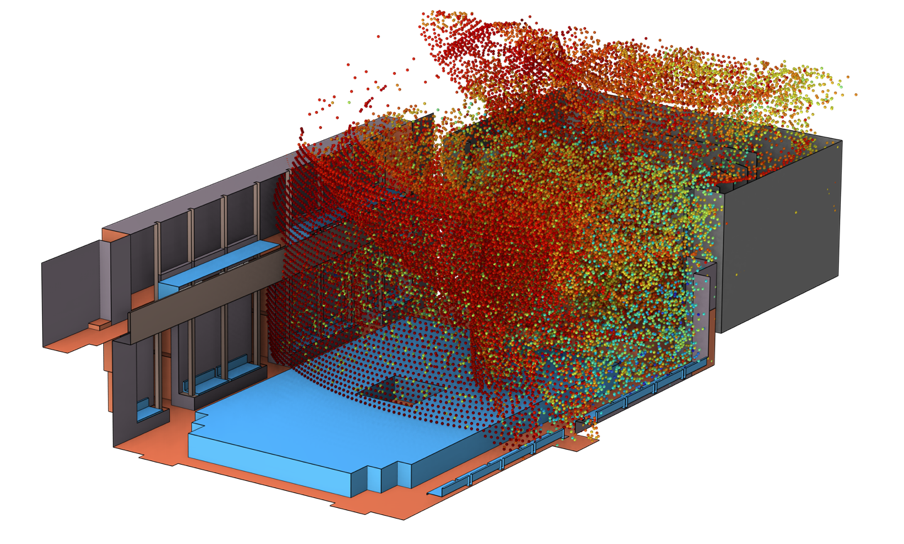
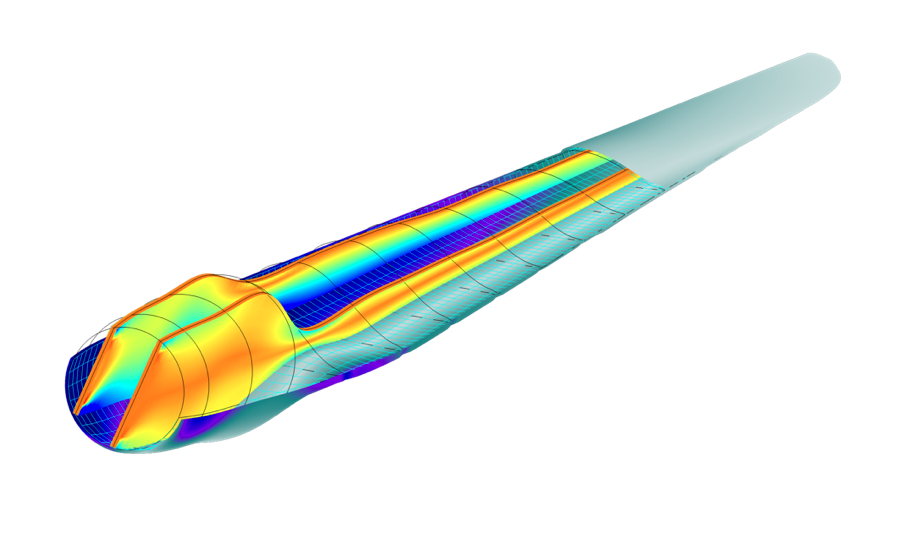
We have been discussing the ways in which you can modify the View node to accentuate points of interest in your model (and simulation results). Another useful aspect of the View node is the ability to hide certain geometric entities in both preprocessing and postprocessing. Again, this is a tool that can be accessed directly from the Graphics toolbar, but the results of the tool’s actions are accessed in the View node. Hiding entities is a technique used in most simulations because more often than not there are walls that block the important results from being seen. Below are three examples where the results would not be visible if we didn’t hide certain parts that are not of interest. Learn how to use the hiding features in our Learning Center article “How to Select Geometry“.
Conclusion and Next Steps
To learn how to use the features discussed in this blog post and more user interface functionality, check out our course on how to navigate the user interface in COMSOL Multiphysics.




Comments (0)