
For as long as people have looked up to the stars, we’ve yearned to see them better. Telescopes extend our vision into celestial places that we could once only imagine. When launched into orbit, telescopes also enable us to study our home planet from a heavenly perspective. Optical telescopes may seem like a mature technology, but demand for improved imagery from both astronomers and the earth observation (EO) sector is growing. One way optical engineers can adapt and refine classic telescope designs is with ray tracing simulation.
Minimizing and Mitigating Optical Distortion
Conceptually, the use of lenses (in refracting, or dioptric telescopes) or mirrors (for reflecting, or catoptric devices) to see distant objects is well understood. In practice, the actual devices that enable us to gather and direct visible light rays also tend to distort them. Minimizing and mitigating distortion within technical and cost constraints is a perpetual challenge for optical engineers. Optical distortion can be minimized through refinements to the optical elements themselves, and it can be mitigated through careful selection and arrangement of these elements inside a telescope.
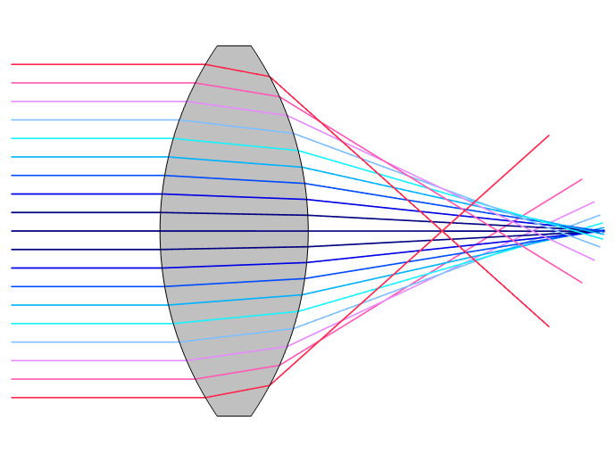
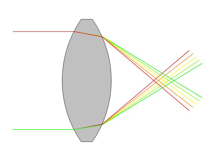
Distortions introduced by optical elements include spherical (left) and chromatic (right) aberrations.
Chromatic aberration occurs because different wavelengths of light are refracted in different directions when passing through a lens. Most real-world materials exhibit optical dispersion: Their refractive indices depend on the wavelength or frequency of light passing through them. Spherical aberration occurs because light passing through (or reflecting off) the edge of a spherical lens (or mirror) crosses the optical axis at a slightly different location, compared to light passing though (or reflecting off) the center. Mirrors do not inherently cause chromatic aberration, but spherical mirrors and lenses both cause spherical aberration.
Even a well-designed telescope made with the finest mirrors and lenses will face distortion due to environmental conditions. Varying temperatures will change the behavior of the materials used to make lenses and mirrors. Physical deformations in the optical system, either due to thermal stress or other applied loads, can also significantly affect the image quality. In addition to these multiphysics factors, the refractive effects of Earth’s atmosphere must be accounted for, along with distortions of optical elements caused by gravity itself.
Analyzing 3 Telescope Designs in COMSOL Multiphysics®
The COMSOL Multiphysics® software and add-on Ray Optics Module support ray trace analyses of telescopes. Using tutorial models of the popular Schmidt–Cassegrain and Gregory–Matsukov designs, along with the innovative segmented-mirror Keck Telescope, we can illustrate the inherent challenges of telescope design and engineering.
Of the three modeled designs, the Schmidt–Cassegrain and Gregory–Matsukov telescopes are ingenious catadioptric hybrids of refracting and reflecting elements, which makes them relatively affordable mass-produced options for astronomy and earth observation. By contrast, the Keck’s designers pushed the limits of optical engineering in creating what was, at the time, the world’s largest astronomical telescope. Since completion in the early 1990s, the two Keck Telescopes have also been steadily improved through the use of adaptive optics (AO) to counter environmental distortions. AO is becoming more common in astronomical telescopes, as well as military, biomedical, robotic, and consumer device applications.
Schmidt–Cassegrain and Gregory–Matsukov: Avoiding Asphericity
The evolution of telescopes has been driven by advances in manufacturing, as well as our growing understanding of light and its behavior. For example, the potential benefits of mirror-based telescopes were demonstrated by Isaac Newton, James Gregory, and Laurent Cassegrain in the 17th century, but instrument makers found it difficult to produce mirrors of sufficient quality with the materials available at the time.
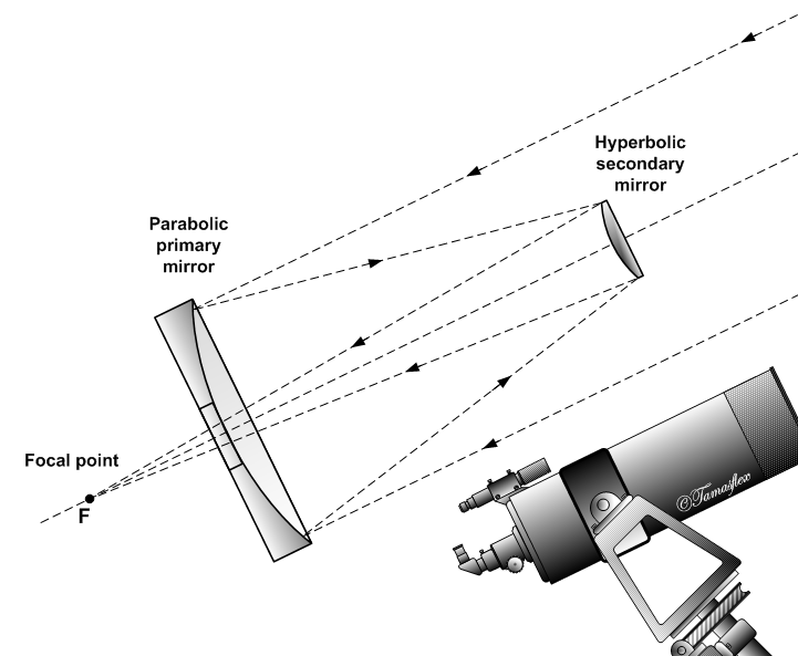
The “classical Cassegrain” catoptric telescope. Image by Szőcs Tamás — Own work. Licensed under CC BY-SA 2.5, via Wikimedia Commons.
Most catoptric designs combine two aspheric mirrors:
- Parabolic primary
- Hyperbolic secondary
This design was first proposed by Laurent Cassegrain in 1672, though the difficulty of producing high-quality mirrors slowed its adoption. In the 20th century, designs such as the Schmidt–Cassegrain and Gregory–Matsukov added a lens to enable the use of spherical mirrors, which remain cheaper to produce.
Technological advances in the late 19th century enabled limited production of Cassegrain catoptrics. That era of rapid scientific progress also introduced new mathematical tools for optimizing telescopes. As explained by optical device manufacturing specialist R.F. Royce:
In 1906 Martin Schwartzchild, a German physicist and optical scientist, published a set of equations that defined the characteristics of two mirror telescopes. Applied to the Cassegrain design these relatively simple formulas began to reveal the fact that by juggling the asphericity between the two mirrors, off axis aberrations could be controlled…This was the first time in history that the concept of optimization in the reflecting telescope was understood in a truly scientific sense.
Even into the 20th century, the catoptric “classical Cassegrain” remained relatively expensive to produce because of its reliance on aspheric mirrors. To address this, Bernhard Schmidt added an aspheric lens, known in this application as a “Schmidt corrector plate”, to the front of the telescope. This catadioptric adaptation enabled the use of spherical primary and secondary mirrors, as the aspheric lens can effectively correct the mirrors’ potential distortion. This approach provides many of a Cassegrain’s advantages at a reduced cost.
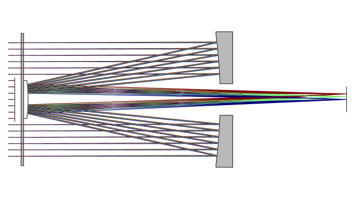
The Schmidt–Cassegrain replaces a Cassegrain’s two aspheric mirrors with spherical primary (at right) and secondary mirrors. A Schmidt corrector plate corrects the distortion that would otherwise be caused by the spherical mirrors. Although the Schmidt corrector plate is an aspheric lens, the variations in surface sag across its surface are too small to see clearly in this geometry.
As shown below, the Gregory–Maksutov telescope’s optical arrangement is similar to that of the Schmidt–Cassegrain. The most significant distinction between the two is that the Gregory–Maksutov substitutes a concave spherical corrector lens for the aspheric Schmidt corrector plate. Dmitri Maksutov proposed the use of a concave corrector lens to make Cassegrain-type telescopes more affordable in the 1940s.
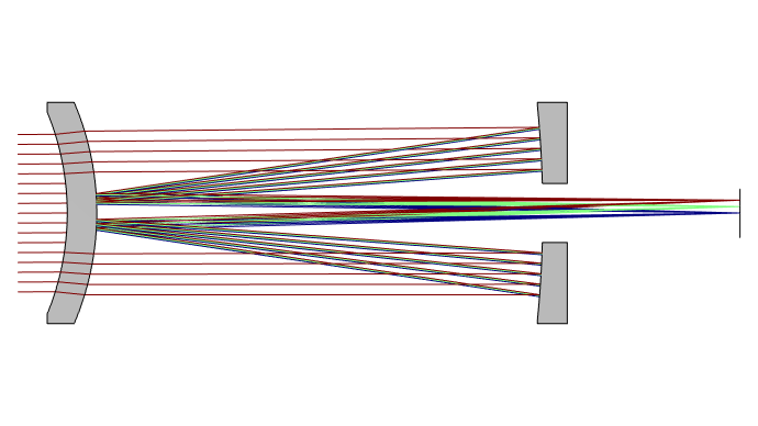
In the Gregory–Maksutov telescope, the secondary mirror is replaced by an aluminized reflective “spot” on the inside of the corrector lens. This cost-effective design is sometimes called a “Spot-Maksutov.”
In 1957, optical engineer John Gregory established the now-popular design of the Gregory–Maksutov telescope. The design’s secondary mirror is, in fact, an aluminized reflective surface applied directly to the inside surface of the concave spherical corrector lens.
The Keck Telescope: 36 Mirrors Acting as One
“A great observatory like the Keck is one of those human achievements which, like the Large Hadron Collider, the Human Genome Project, William Shakespeare and Franz Schubert, render me tearful with pride at belonging to the species Homo sapiens.”
– Richard Dawkins
While the other designs described here have helped bring telescope costs down to Earth, the creators of the Keck were aiming for the stars, in every sense of the phrase. Its 10-meter mirror is twice the size of that of the Hale Telescope, which had been the largest in the US since 1948. There are actually two of these behemoth telescopes, installed in 1992 and 1996 at the Keck Observatory on Hawaii’s Mauna Kea Summit.
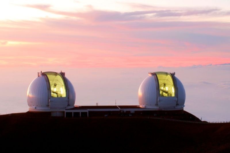
The two Keck Telescopes at Mauna Kea Observatory, Hawaii. Image by SiOwl — Own work. Licensed under CC BY 3.0, via Wikimedia Commons.
Despite the scale of the project, the Keck’s designers faced some of the same constraints as more modest telescopes. Even as our capabilities improve, it remains difficult to build large, precise mirrors. In the 1970s, the University of California/Caltech team that developed the Keck estimated that a single 10-meter mirror would cost more than $1 billion, or more than $3.6 billion today.
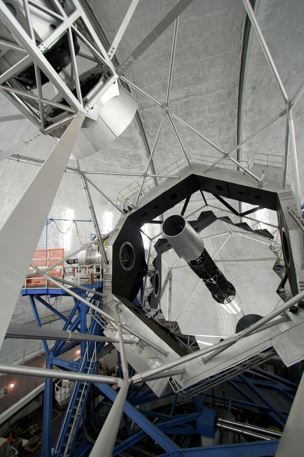
The segmented mirror of the Keck Telescope. Image by SiOwl — Own work. Licensed under CC BY 3.0, via Wikimedia Commons.
To avoid these exorbitant costs, astrophysicist Jerry Nelson of UC Berkeley proposed breaking the team’s massive mirror-making problem into smaller pieces, literally. The Keck’s parabolic reflective surface is made from 36 separate interlocking mirrors, all acting in concert through near-constant mechanical adjustment.
To appreciate how powerful yet precise this system is, consider that each 1.8-meter-wide segment weighs about half a ton, and every segment is aligned twice per second to an accuracy of 4 nanometers — about 1/25000th the diameter of a human hair. While the resulting assembly is certainly massive, the segmented mirror assembly weighs about the same as the 5-meter Hale mirror, even though it covers four times the surface area.
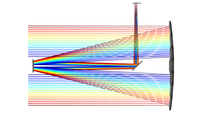
Schematic of the overall design of the Keck Telescope, with segmented primary mirror at right.
The constant adjustment of its primary mirrors effectively mitigates the distortions caused by gravity, and its adaptive optics system helps the Keck counter atmospheric distortions. The secondary mirror is adjusted up to 2000 times per second. This improves its resolution by a factor of 10, and its sensitivity to distant stars by a factor of 100.
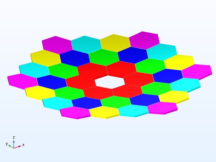
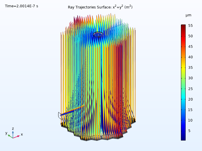
Left: The Keck Telescope primary mirror geometry, as constructed using instances of the Conic Polygonal Mirror Off Axis 3D part from the Ray Optics Part Library. It consists of 36 hexagonal segments with a common parent surface. There are 6 unique mirrors, each replicated 6 times in a 6-fold rotational pattern. Right: Ray diagram of the Keck Telescope colored by radial distance from the centroid.
Look Further into Telescope Design with Simulation
The Ray Optics Module enables you to efficiently construct models and perform ray tracing analyses of telescope designs. This module includes a built-in Part Library of parameterized geometry subsequences that you can load into your COMSOL models. Our tutorial model of the Schmidt—Cassegrain telescope, for example, is created using an instance of the Aspheric Even Lens 3D part, whereas the Spherical Mirror 3D part is used to create the primary and secondary mirrors. A built-in library of optical parts makes it significantly quicker and easier for optical designers to set up their models.
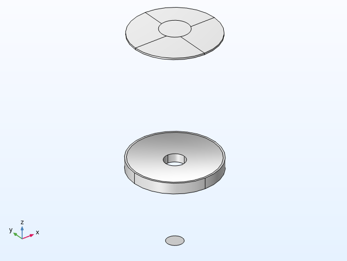
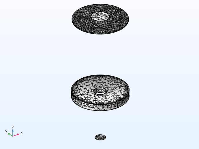
The Schmidt–Cassegrain telescope assembly, with mesh applied to the model. Note that the optical prescription has been reformatted to allow these parts to be defined in a somewhat arbitrary sequence; that is, the order in which optical elements are placed in the geometry sequence does not affect the ray trace. However, the optical elements can be placed relative to one another by making use of built-in workplanes in each of the Part Instances.
Light waves propagating through a telescope model are treated by the COMSOL® software as rays. These rays can be reflected, refracted, or absorbed at any boundary in the model geometry. The Ray Optics Module provides multiple visualization options for presenting such simulation results. The examples below present a ray trace using three wavelengths (486 nm, 546 nm, and 656 nm) at three field angles (0, 0.125, and 0.25 degrees).
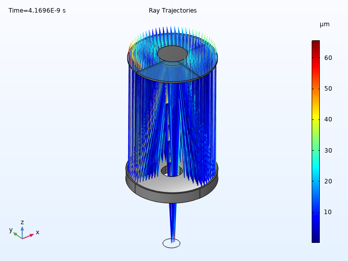
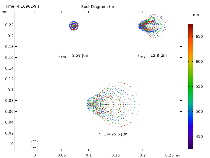
Left: Ray diagram for the Schmidt–Cassegrain telescope, showing the resulting ray trajectories. The Color Expression represents the ray positions on the image surface. Right: Spot diagram colored by wavelength. The Airy disc is shown for reference in the lower-left corner.
You can also account for the environmental factors that affect image quality with add-on tools for performing a structural-thermal-optical performance (STOP) analysis within a single simulation environment.
Next Steps
Download the tutorial models for the three telescope designs discussed here:


Comments (0)