
In the 1970s and 80s, music fans would dedicate entire rooms of their homes to stereo systems. Big, boxy loudspeakers were essential fixtures of these stereo setups. Today, a new trend has emerged: Consumers want loudspeakers that are both powerful and portable, with the ability to connect to devices around the house and on the go. To design sophisticated yet lightweight loudspeakers, you can optimize the topology of their components, such as a magnetic circuit for the loudspeaker driver.
The Power of Portability in Loudspeaker Design
Current loudspeakers feature advanced connectivity and an improved frequency range. This enables them to interact with virtual assistants; stream music wirelessly; and connect to additional parts, such as subwoofers. These advancements create new design demands. For instance, some loudspeakers are waterproof so that they can be used while in the shower or by the pool. Perhaps a more serious concern is that loudspeaker designs should be durable so that consumers can start using the product right out of the box.
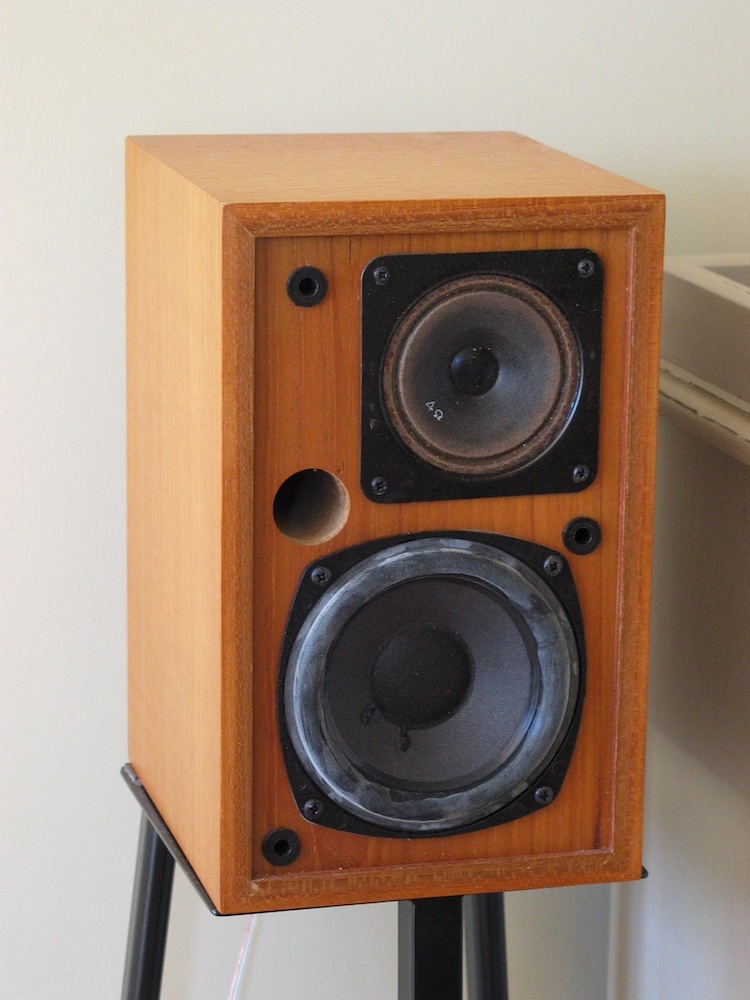
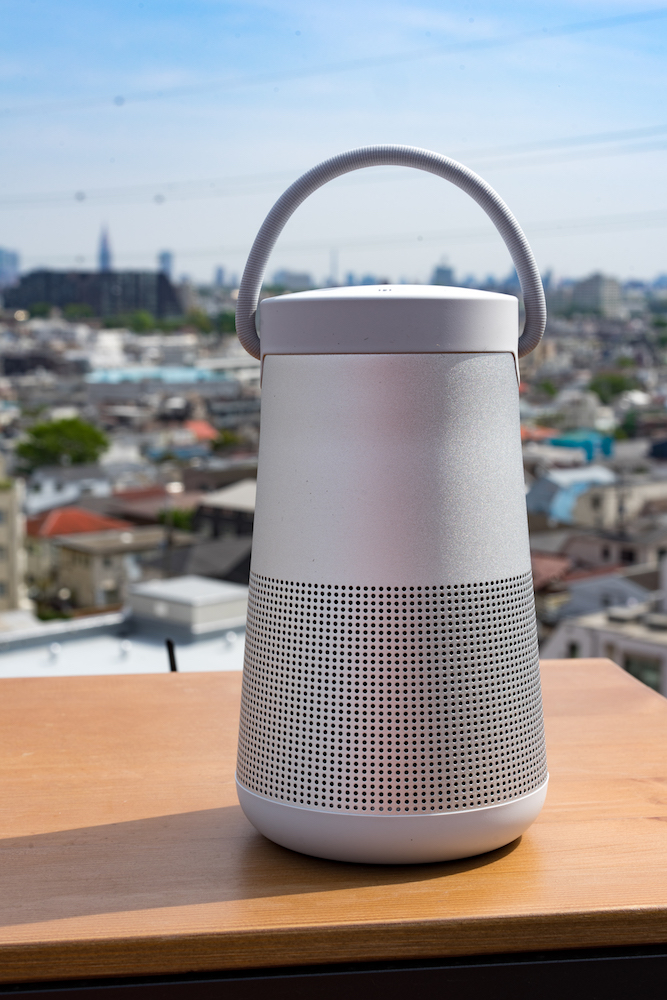
Left: A loudspeaker with the grille removed, circa 1980s. Image by By PT35 — Own work. Licensed under CC BY-SA 3.0, via Wikimedia Commons. Right: Example of a modern, portable speaker with Bluetooth® wireless technology. Image by TAKKA@P.P.R.S. — Own work. Licensed under CC BY-SA 2.0, via Flickr Creative Commons.
Portability is one design factor that has become almost a requirement as consumer preferences change. Engineers need to design smaller, lighter loudspeakers that maintain sound quality and performance standards. To maximize loudspeaker performance while minimizing the overall weight, you can perform a topology optimization of loudspeaker driver components using the COMSOL Multiphysics® software and add-on Optimization Module.
Optimizing a Magnetic Circuit Design with COMSOL Multiphysics®
In a loudspeaker driver, a magnetic circuit concentrates the magnetic flux into an air gap. A coil is placed in the air gap that winds perpendicular to the magnetic flux lines and is mechanically connected to the membrane of the speaker. When a current runs through the coil, electromagnetic forces induce movement. The membrane picks up this movement and interacts with the air, generating sound waves.
The magnetic circuit is constituted by an iron yoke, which performs two important functions:
- Maximizing the flux concentrated at the coil
- Providing a uniform field across the coil
In this example, the geometry for the circuit is similar to the one in the Loudspeaker Driver model. It is convenient to formulate the iron’s constitutive relation as a nonlinear relative magnetic permeability \mu_r(B) derived from its original B-H curve. This paves the way for the topology optimization, where the permeability will easily combine with the control variable field to drive the optimization process.
To determine the optimal shape of an iron yoke for a magnetic circuit, you can use topology optimization.
A typical figure of merit for the performance of the magnetic circuit is the parameter BL, or force factor, which is the product of the magnetic flux in the air gap and length of the coil. The larger the BL parameter, the higher the performance of the magnetic circuit. For a multiobjective study, you can scan the optimal shape for the component as a function of BL together with the weight reduction of the yoke.
After the topology optimization solution is found, you can extract the optimized geometry and reconstruct it for further analysis.
Evaluating the Performance and Design of the Magnetic Circuit
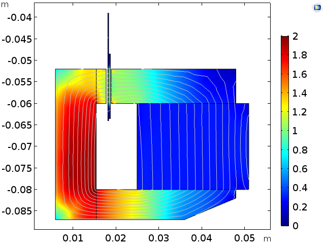
The original geometry includes an iron domain with a volume of 37 cm3; specifically, the lower arm of the iron yoke. In the first two studies, the magnetic fields for the initial (suboptimal) circuit configuration are analyzed and the nonlinear relative permeability approach is validated by comparing magnetic fields with the standard B-H formulation.
Left: The original geometry (red: iron, blue: air). Right: Magnetic flux density norm and lines for the initial configuration.
Topology Optimization of the Magnetic Circuit
By adding an Optimization interface, you can further reduce the volume of the iron yoke while preserving a high magnetic performance.
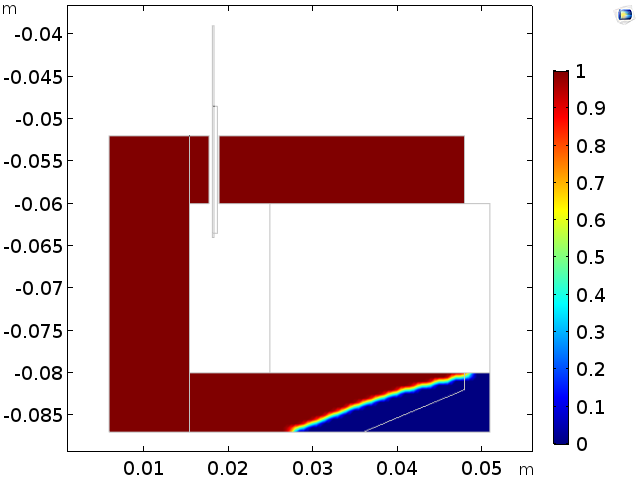
The third study begins with a two-step topology optimization, always seeking the highest possible BL and starting from a “full” cylindrical annulus with an iron volume of about 52 cm3. The former condition is implemented as an integral objective on the Coil domain; the latter as an integral inequality constraint, where it is required that the volume of the yoke remains as close as possible to the target volume.
A reduction to 37 cm3 is targeted in Study 3 and the result, very similar to the original geometry, confirms that the original geometry was indeed already nearly optimal. Study 4 seeks the best performance with an even lighter geometry, expressed as a filling factor of 50% of the full volume; i.e., 26 cm3.
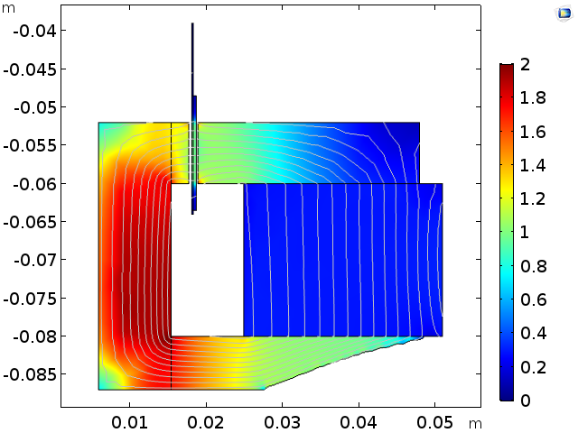
Left: The optimized geometry, where the volume of the lower arm of the iron yoke is 26 cm3. Right: Magnetic flux density norm and lines for the optimized configuration.
The results for the two studies are comparable. Although the geometry with the optimized topology is lighter, there is no drawback in performance.
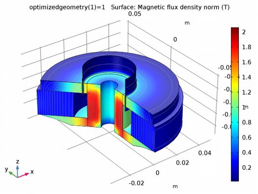
A 3D revolution plot of the magnetic flux density norm, showing the final optimized geometry.
These studies show that topology optimization can be used to find the best possible shape and constraint parameters for a loudspeaker component.
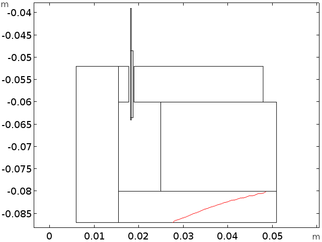
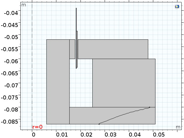
In preparation of further analyses on the optimal configuration, the final shape of the optimization analysis can be exported as an independent geometry.
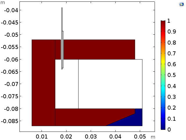
Left: A contour plot that defines the optimized iron/air threshold. Right: The optimized shape imported as a geometry object.
Next Steps
Click the button below to try the Topology Optimization of a Magnetic Circuit tutorial yourself.
Read more about topology optimization:
- How to Use Acoustic Topology Optimization in Your Simulation Studies
- Acoustic Topology Optimization with Thermoviscous Losses
- How to Use Topology Optimization Results as Model Geometries
The Bluetooth word mark is a registered trademark owned by the Bluetooth SIG, Inc. and any use of such marks by COMSOL is under license.



Comments (0)