
Did you know that the COMSOL Multiphysics® software allows you to have different discontinuous meshes in neighboring domains? Although the usual default behavior of the software is to use aligned meshes, there are times when we might like to have discontinuous meshes, such as for modeling conjugate heat transfer. Let’s delve deeper into this topic and see how these meshes can save us time and memory in our initial model development with just a little bit more effort.
Maintaining the Continuity of the Fields and Balancing the Fluxes Between Aligned Elements
The basic theory behind the finite element method (FEM) has been covered several times (such as in this blog post on the weak form), so we won’t go over it all here. Instead, we will review one key point: What happens at the interface between different finite elements? In short: When the standard FEM is used, adjacent aligned elements share the same node points (the node points are the points at which the solution to the problem is computed). Since these elements share nodes, the fields being solved for (such as temperature, solid displacement, fluid velocity, etc.) are automatically continuous.
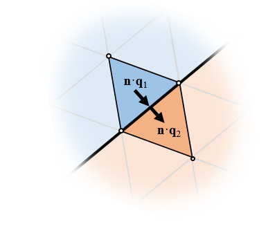
Fluxes are automatically balanced between elements of different domains and these elements share the same nodes, so the fields are continuous.
Furthermore, the fluxes are naturally enforced to be equal (although this requires a bit more thorough understanding of the derivation of the FEM). Now, the term flux can refer to different quantities, depending upon the physics we are working with. For brevity, we will just consider heat transfer, where we naturally speak of the heat flux, which is the thermal conductivity times the negative of the gradient of the temperature field, or \mathbf{q} = -k \nabla T. At boundaries between elements, the FEM automatically (that is, without needing any user input or additional internal equations) enforces the condition that \mathbf{n \cdot q_1 =n \cdot q_2 }, where \mathbf{n} is the normal vector to the boundary between elements. That is, the standard FEM naturally enforces the continuity of the fields and balances fluxes. Do keep in mind that, regardless of this, you will always need to do a mesh refinement study to gain confidence in the overall accuracy of your model.
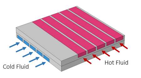
Schematic of a submodel of a cross-flow heat exchanger.
Let’s now take a look at a sample model from the Application Gallery, the Cross-Flow Heat Exchanger, which is schematically pictured above. This is a submodel of a larger heat exchanger consisting of straight rectangular channels. The fluid flow through the channels is modeled, as is the temperature field in the fluid and the surrounding solid. The temperature field is plotted below. The temperature is also plotted along a representative line along the length of the flow channel. Observe from these plots that the temperature variation along the flow channel is varying quite slowly along the length, quickly over the cross section of the flow channel, and in a quite complicated way through the metal part.
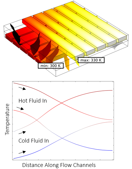
Temperature field at the walls and isosurfaces of temperature in the solid (top) and the plots of temperature along the flow channel directions (bottom).
The mesh is plotted below, and we can see that it is continuous between the fluid domain and the solid domain. The mesh is composed primarily of tetrahedral elements, with a boundary layer mesh applied on the fluid side of the channel walls to resolve the high velocity and thermal gradients near the wall.
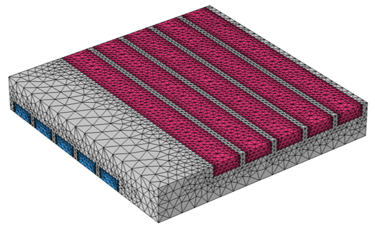
Default mesh of the cross-flow heat exchanger that is continuous between the fluid and solid.
Now, this default mesh is generated with no user interaction at all. But what if we wanted to manually build the mesh, and what if we allowed the mesh to be discontinuous — what could we do then? Before we get to how to implement that, let’s take a look at what the software will need to do.
Maintaining the Continuity of the Fields and Balancing the Fluxes Between Nonaligned Elements
Suppose we have a set of elements on two adjacent domains, as shown in the image below. The elements have adjacent boundaries, but the nodes are nonaligned. This kind of mesh is automatically generated when the Form Assembly geometry finalization step is used. The meshes of separate objects will not be connected, so as a consequence, the fields across this boundary will be as discontinuous, with no flux between the domains.
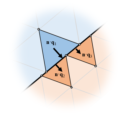
For nonaligned meshes, additional equations must be introduced to approximately balance fluxes and fields.
However, the Form Assembly operation can also automatically create so-called Identity pairs at the adjacent boundaries between objects. Within each physics, you can then apply boundary conditions to these pair boundaries. Depending upon the physics interface, different boundary conditions will be available, but in all cases, the Pair Continuity condition will be available. This condition enforces the continuity of the fields, and the fluxes, across the boundary in an element-averaged sense. It does so by adding an additional set of equations behind the scenes, which we won’t go into here. Since the elements are not exactly aligned, the fields and fluxes cannot be pointwise continuous, which is a drawback; however, we can now have different meshes in adjacent domains, which has advantages. Let’s look at how this benefits us in the case of this cross-flow heat exchanger.
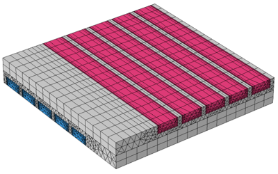
As we saw earlier, the temperature variation along the flow channel is quite gradual. Since the flow is laminar and the channels are uniform in cross section, we also know that the flow field is nearly invariant along the flow directions. Therefore, we can apply a swept mesh in the channels along the direction of the flow, as shown in the image below. Observe that far fewer elements are used in the flow direction, thereby reducing the problem size with only a small loss in accuracy as compared to the previous mesh.
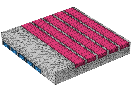
With assembly meshing, a swept mesh in the fluid channels allows for an elongated mesh with fewer elements.
Now, there are a few additional manual steps that we have to take to set up this mesh. First, within the Geometry sequence, we have to define two different objects. The first object is the metal part, the solid through which the fluid flows. The second object is the combination of all of the fluid flow domains; that is, a single object that is composed of several different domains, which are created via Boolean Union operations in the geometry sequence. We do need to ensure that these domains are nonoverlapping for the Form Assembly finalization operation to be valid, and then the software will automatically recognize all mating faces between these objects as identity pairs.
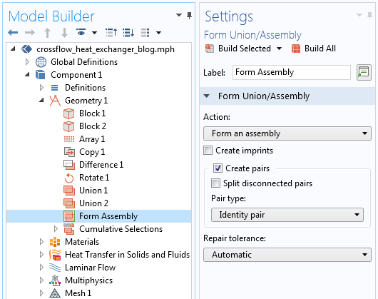
The Form Assembly geometry finalization that automatically creates Identity pairs.
Next, within the Heat Transfer in Solids and Fluids interface, we need to add a Pair Continuity boundary condition. Since we only have two adjacent objects (the solid and all of the fluid domains), this condition needs to be applied just to a single Identity Boundary Pair. No other changes to the physics are necessary.
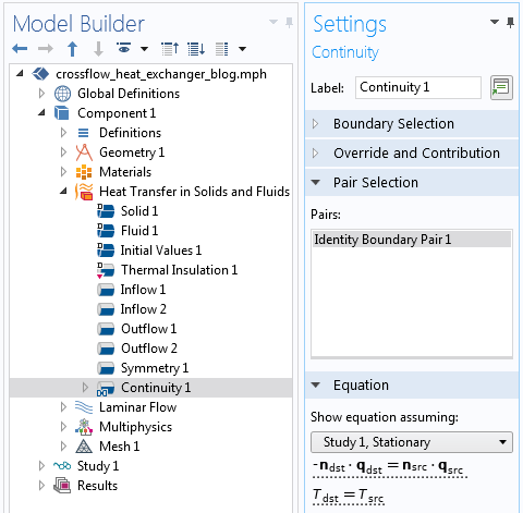
The Pair Continuity boundary condition that enforces continuity of fields and balances fluxes.
Finally, the Mesh sequence has to be manually modified. The default meshing sequence will copy the elements on the mating faces of the pair boundary, but we will want to disable this and apply a swept mesh that is elongated along the length of the flow channels. Since we know the solution varies quite gradually in this direction, the modification is justified. No other significant changes are made to the mesh, as compared to the automatically generated mesh shown earlier.
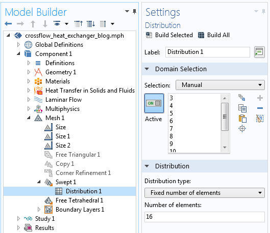
The meshing sequence used to control the number of elements along the flow directions in the channels.
The temperature field and the difference in the temperature field are plotted below. The model using the swept mesh is, of course, going to be different. In this case, the temperature field differs by about 2°C in some regions compared to the previous case. This difference is primarily due to the difference in the mesh across the interface. It is not due to the additional pair continuity equations. In the limit of mesh refinement, both approaches will converge to the same solution. The primary advantage of using assembly meshing is that you can begin with a relatively coarser mesh that will still give reasonable results, thereby saving time and computational resources in your initial model development.
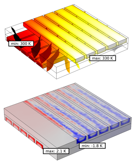
Temperature field (top) using assembly meshing and the difference in this temperature field (bottom) as compared to the default mesh.
In the case of this geometry, we could also divide our geometry in a different way. We could split our model up into two objects along the plane between the flow channels, as shown in the image below. Now, we can lower the element count even more. Although not all geometries lend themselves to this subdivision, this approach can even further reduce the element count.
An alternative meshing strategy would introduce the identity pair within the solid rather than at the fluid-solid boundary.
Closing Remarks
We have shown here that assembly meshing is a useful technique for reducing the number of mesh elements. This is particularly applicable for conjugate heat transfer problems, since these often contain relatively uniform flow channels that lend themselves to swept meshing. Although here we have considered a model involving laminar flow, this approach will also work for turbulent flow problems. Keep in mind, though, that this technique has its place in preliminary model development: You’ll usually want to verify these models against a model with a congruent mesh and, of course, always do a mesh refinement study. The key advantage is that you can more quickly do preliminary analyses.
The model using the assembly meshing capability is available for download here:


Comments (4)
Hamza Ramdani
November 24, 2018good work please can i have mode details about the steps for the mesing
Brianne Costa
November 27, 2018 COMSOL EmployeeHello Hamza,
Thank you for your comment.
For questions related to your modeling, please contact our Support team.
Online Support Center: https://www.comsol.com/support
Email: support@comsol.com
Luiz Fernando de Oliveira
March 9, 2019Hi! Very nice work. In the case I’m thinking, consider a simulation of a Epstein Frame test with thin sheets. Even with so small dimensions, the sheets mesh can be done very efficiently using some Mapped Quad Mesh, but in the interface to the Free Tetrahedral of the surrounding region, it generates many elements. Can it be used for this kind of magnetic simulations?
Brianne Christopher
March 11, 2019 COMSOL EmployeeHello Luiz,
Thank you for your comment.
For questions related to your modeling, please contact our Support team.
Online Support Center: https://www.comsol.com/support
Email: support@comsol.com