
Today, guest blogger Thomas Clavet of EMC3 Consulting, a COMSOL Certified Consultant, discusses simulating phased array and geometrically focused probes.
Ultrasound focusing is widely used in various industrial applications, such as nondestructive testing (NDT) and medical imaging. For clinical applications, high-intensity focused ultrasound (HIFU) is a specific aspect of this technology where most of the power provided by the probe is carried to a targeted zone to coagulate biological tissues. This blog post discusses ultrasound focusing simulation.
Designing Transducers for Noninvasive Ultrasounds
Ultrasounds have a great advantage: They can reach a volume inside a piece of metal, a human organ, or biological tissue without the need to cut through the path of the transmitted signal to the target at which it is directed. Unlike the scalpel of a surgeon in a medical treatment, ultrasound will not leave any scarring on the skin of a patient and can still treat the targeted zone with good accuracy, while limiting the risk of damage to the surrounding healthy tissues. Focused ultrasound is used or has the potential to be used to treat diseases like prostate and breast cancer, hypertension, and even glaucoma.
There are several ways to focus ultrasound using different transducer designs, and the COMSOL Multiphysics® software is a very good tool to simulate and optimize them. Designing a transducer that will effectively produce an ultrasound field that reaches a targeted zone can be a difficult task. It depends on the frequency and power of the emitted signal; the attenuation and absorption of the medium in which the ultrasound propagates; and, of course, the position and dimensions of the transducer itself.
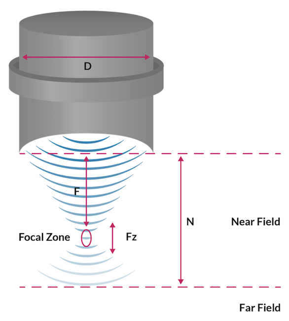
Figure 1: Schematic of the acoustic field generated by an ultrasound transducer.
Here are a few important aspects of an ultrasound transducer used for clinical applications (see figure above):
- The near field distance N, calculated as: N={D^2 f}/{4c} (1)
- D is the transducer diameter
- f is the frequency
- c is the speed of sound in the medium
- The focal distance F, which is the distance between the transducer and the focal point that is the targeted zone
- The field depth or focal zone, which defines the -6-dB signal amplitude drop from the maximum amplitude, calculated as: F_Z=\frac{2F^2}{N+{\frac{F}{2}}} (2)
Two alternatives can be used to focus the signal from the transducer:
- Modify the radius of curvature of the transducer element to a value corresponding to the focal distance (see the above schematic)
- Introduce a phase delay when applying voltage in an array of several flat-faced transducers (see schematic below)
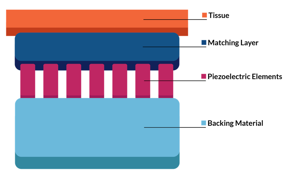
Figure 2: Schematic of an ultrasonic probe with an array of piezo transducers (phased array) used to focus the acoustic signal. The transducer consists of a backing material, the piezo elements, and a matching layer to the tested sample (here tissue).
COMSOL Multiphysics has been used to look at these two alternatives. Besides the ability to model ultrasound propagation, it is also very interesting to couple this simulation with a heat transfer simulation and even a damage law of biological tissues. In this way, we can quickly visualize whether the focusing effect can treat the right amount of tissues and check the location and volume of coagulation, all within the same modeling interface.
Simulating a Geometrically Focused Probe
Ultrasound can be focused directly by the way the emitting transducer is shaped. A tutorial available with the Acoustics Module provides a very good example of this phenomenon coupled with heat transfer. A few assumptions are made to the acoustics simulation, such as neglecting the nonlinear effects and shear waves, but it still provides very valuable information about the sensitivity of the focal zone to the probe parameters.
This tutorial can be adapted to most device configurations and used as a starting point for simulations. For instance, before running the heat transfer part of the simulation, we can check how the frequency modifies the size of the focal zone, hence the energy that is delivered to this zone. In the example below, three frequencies are computed at 0.5 MHz, 0.7 MHz, and 1 MHz. Figures 3–5 show the shape of the ultrasound pressure wave, the size of the focal zone with the criteria max(SPL) – 6dB, and the corresponding energy that is used to heat and coagulate tissues, respectively.
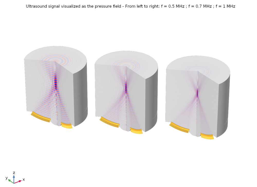
Figure 3: Simulated ultrasounds (represented in blue and red wave-type signals) are emitted and focused by a curved transducer (the surface with orange arrows at the bottom). They travel in tissues and provide a peak of intensity in the focal zone. This results in an elevation of temperature due to the absorbed energy.
When the transducer diameter and curvature are kept constant, increasing the frequency will reduce the size of the focal zone. We clearly see the smaller wavelength at a higher frequency, as well as its effect on focusing.
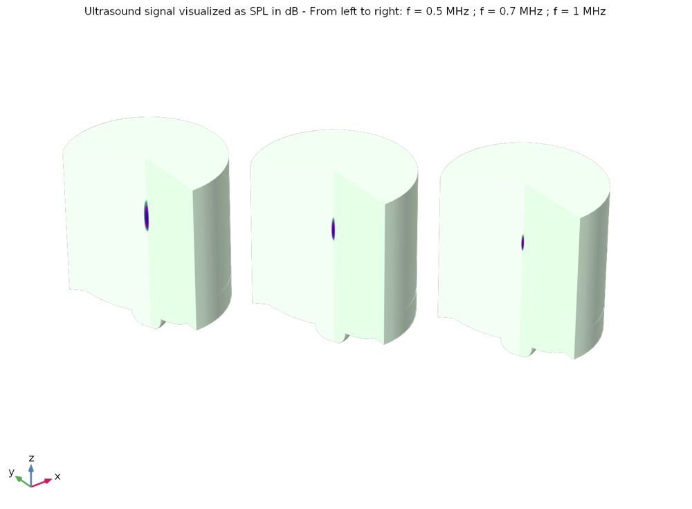
Figure 4: The size of the focal zone is visualized with the max(SPL) – 6dB criteria. It confirms what can be seen from the pressure plot above. The dB scale is not the same for the three visualized frequencies.
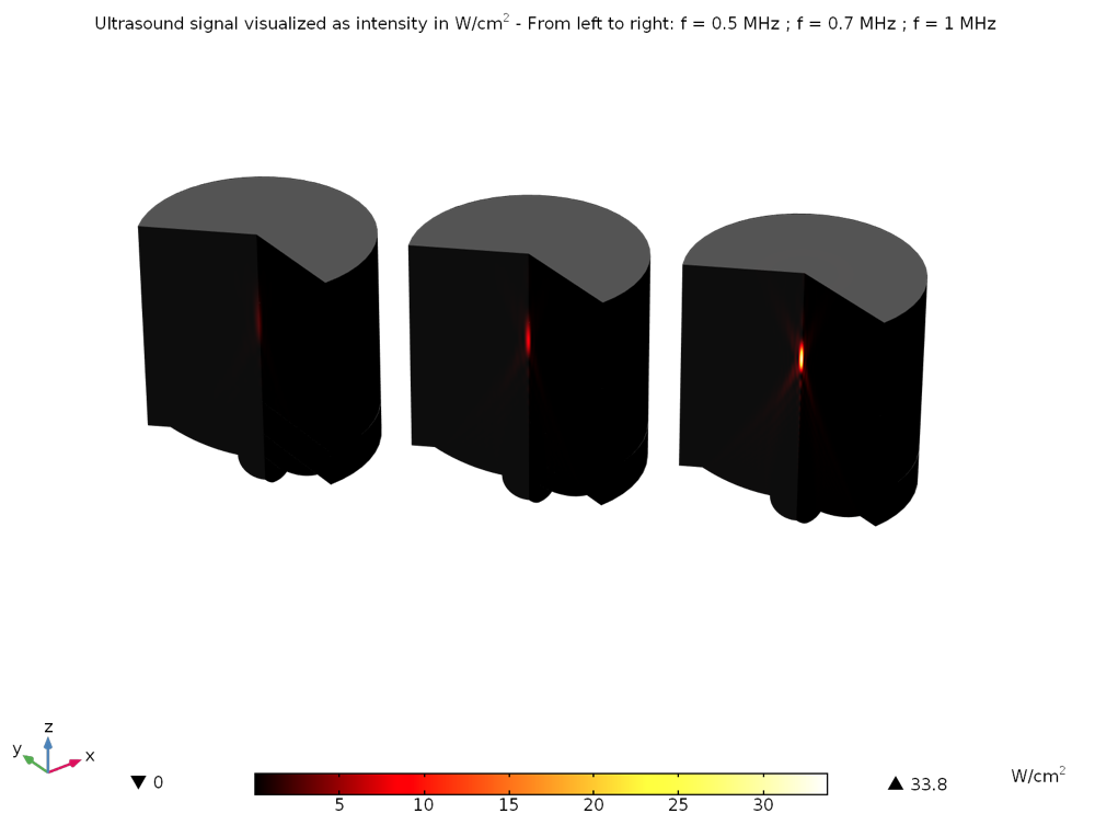
Figure 5: The acoustics intensity is plotted for all three frequencies on the same color scale in W/cm2. The maximum intensity deposited is more than 10 times higher at 1 MHz than at 0.5 MHz, with all other parameters kept equal. Although the focal zone is decreased when increasing the frequency, it also means that more energy is transmitted to this zone, hence allowing for higher temperatures in the tissues.
Phase Delay Focused Probes
Another way to focus ultrasounds is to use several transducers in an array of piezoelectric elements and then control the voltage input with a phase delay for each element. This phase delay must be calculated for each array configuration, since it depends on frequency, piezoelectric elements, size, position, and, of course, on the focal distance.
For a linear array of elements, a quick method is to consider the distance di between the center of each element i and the focal point and to apply the phase as:
(3)
To illustrate this, let us make a geometry of a 16-element array probe and use the Acoustics Module and Heat Transfer Module with COMSOL Multiphysics to couple several interfaces:
- Pressure Acoustics, Frequency Domain
- Solid Mechanics
- Electrostatics
- Bioheat Transfer
The geometry is shown in a 2D cross section in Figure 6 below, with matching and backing layers in front of and behind the piezoelectric elements, respectively. The backing layer is used to prevent excessive vibrations. The matching layer is an intermediate material between the piezoelectric material and the biological tissue that is necessary for ultrasonic waves to efficiently enter the tissue. It has the same function as the gel used by a doctor between the probe and the skin for an echography.
Figure 6 also shows the phase delay that has been calculated based on (3) as a color and deformation plot on each element, going from 0 on the side elements to 434° in the centered elements.
When the voltage is applied on these elements, the piezoelectric material vibrates and creates an ultrasound wave that will focus at the desired focal distance due to the phase delay.
As for the geometrically focused probe, this simulation can then be coupled to the heat transfer and damage law simulation to assess the temperature elevation and the coagulated volumes in the biological tissues. The heat source from the acoustics signal, given in the plane-wave limit, is calculated as:
(4)
where αabs is the acoustic absorption coefficient of the tissue and Iac is the acoustic intensity magnitude.
The absorption of energy, represented by αabs, varies significantly with the different tissues. As a result, it is also important to check if the calculated focused signal damages other tissues between the array probe and the focal zone. If these tissues are not supposed to be damaged, then the focus should be modified. In this case, the simulation allows us to quickly modify the design and operation parameters of the array probe and to validate or discard an array configuration.
Figures 7 and 8 show the shape of the ultrasound pressure wave and the corresponding energy that is focused, respectively.
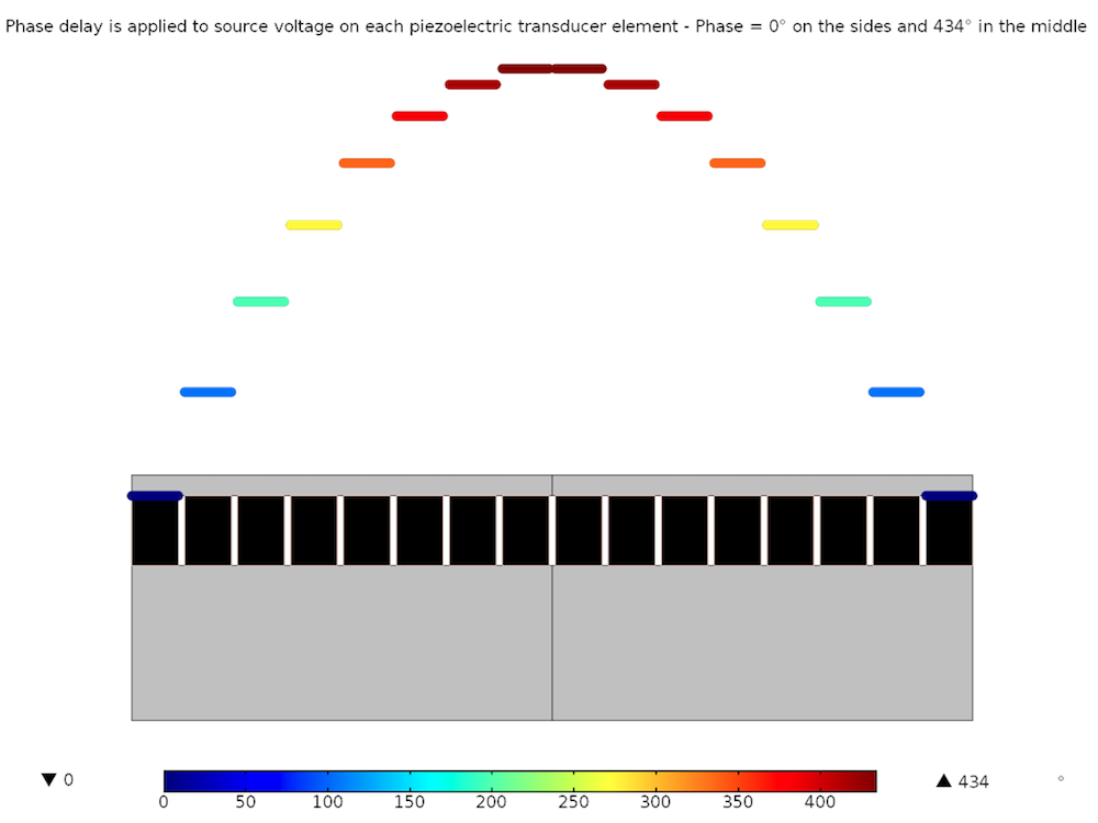
Figure 6: The delay, which is calculated as a function of the frequency, the focal distance, and the size and position of the transducer elements.
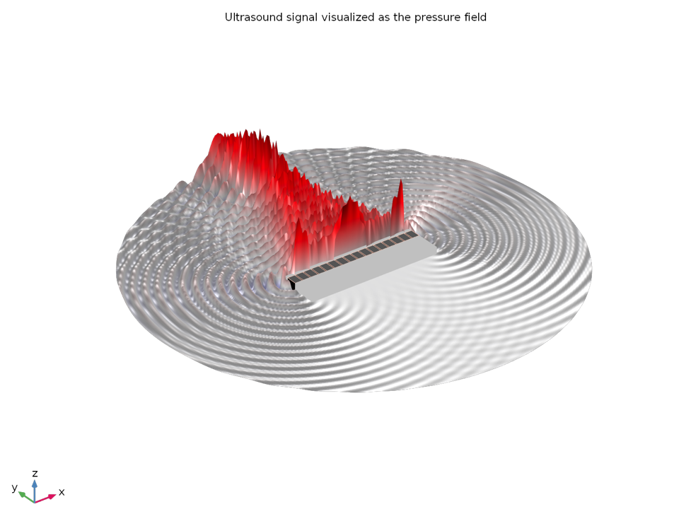
Figure 7: The wave pattern is seen at a frequency of 1.5 MHz. One can decide to modify the geometric design, phase delay, and even the device frequency if the ultrasounds are not focused enough.
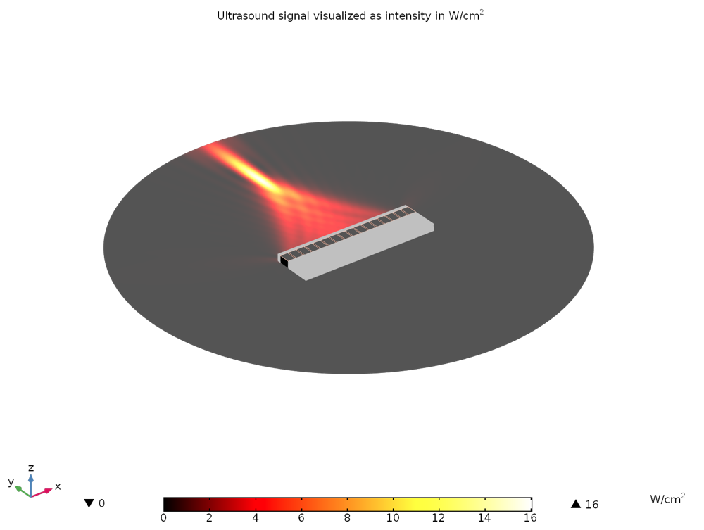
Figure 8: The acoustics intensity is plotted in W/cm2. Here, the 16 piezoelectric transducer elements provide a low intensity that is spread out over a few millimeters on the focal zone. At this stage, the heat transfer and damage simulation could be run to decide if the temperature elevation due to nonnegligible intensity between the focal zone and the transducers (a few W/cm2) is too high or if it could be handled during the medical treatment.
Related Resource
- Read a related paper from the COMSOL Conference 2013 Rotterdam:
References
- Zhenya Yang, Jean-Louis Dillenseger. Phase estimation for a phased array therapeutic interstitial ultrasound probe. Conference proceedings: Annual International Conference of the IEEE Engineering in Medicine and Biology Society. IEEE Engineering in Medicine and Biology Society. Annual Conference, Institute of Electrical and Electronics Engineers (IEEE), 2012, 2012, pp. 472-5.
- “Phased Array Tutorial”, Olympus, http://www.olympus-ims.com/en/ndt-tutorials/phased-array/.
- “Basic principle of medical ultrasonic probes (transducer)”, Nihon Dempa Kogyo Co., Ltd., http://www.ndk.com/en/sensor/ultrasonic/basic02.html.
About the Guest Author
Thomas Clavet is a mechanical engineer from Arts et Métiers Paris Tech and KTH University in Stockholm. He has previously worked as a stress engineer in the nuclear industry and as an application engineer for COMSOL Ltd. in the U.K. and Ireland, where he met and trained several COMSOL Multiphysics users in the fields of fluid flow, heat transfer, acoustics, and structural mechanics simulations.
Thomas founded EMC3 Consulting in 2014, in the south of France, to provide his expertise in the use of COMSOL Multiphysics as a COMSOL Certified Consultant and in the fields of CFD, heat transfer, acoustics, and structural mechanics simulations.
Learn more about how EMC3 Consulting is helping companies to design better products with COMSOL Multiphysics by visiting www.emc3-consulting.com.



Comments (4)
Jack Drummond
November 26, 2018Is there any chance you could share the .mph file for the phased array simulation?
bin shen
September 16, 2019Can you share the .mph file for the phased array simulation with the second method.
Brianne Christopher
November 12, 2019 COMSOL EmployeeHi Bin,
Thank you for your comment. While this MPH-file is not available for download, you may find this example useful: https://www.comsol.com/model/acoustic-streaming-in-a-microchannel-cross-section-17087
You can also contact our Support team for help with your modeling problem:
Online Support Center: https://www.comsol.com/support
Email: support@comsol.com
Song Chang-gun
February 18, 2020Hello.
My name is Song.
I think your information(ultrasonic phased array) will be very helpful to me.
I want to focus using a multichannel phased array.
So, as in information, we are running simulation using COMSOL.
I want to get your COMSOL simulation source files.
This seems to be very helpful.
Please reply.
Thank you.