
This blog post continues our discussion of the terms voltage and ground. Here, we will define and interpret these terms for sinusoidally time-varying models. We look at the case of a transmission line and address how to correctly define voltage and ground in problems involving wave-like fields.
A Simple Transmission Line
We will consider the transmission line shown in the image below: a metal wire that sits in free space above a ground surface (or ground plane, or signal ground), which we will define more precisely very shortly. This falls into the category of a TEM transmission line, meaning that the electric and magnetic fields lie purely in the plane perpendicular to the line, and that the Poynting flux vector is everywhere parallel to the line. (Very strictly speaking, this is a quasi-TEM transmission line, since the metal wire is not infinitely conductive, but as we will see, this point does not alter any aspect of the following discussion.)
At one end of the wire, there is a sinusoidally time-varying source connecting the ground plane to the wire, and at the other end of the wire, there is a resistive load. Although we don’t see this exact transmission line very often in practice, it is similar to a microstrip line.
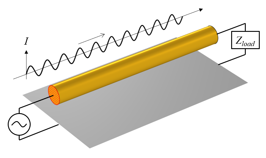
A conductive wire above a ground plane, with a source at one end and a load at the other, along with a plot of the total current in the wire at an instant in time.
The sinusoidally time-varying source will drive current back and forth along the entire length of the wire, through the resistive load and then into, and out of, the ground plane. If we could take a snapshot of the current at any instant in time, it would look like a sine wave propagating from source to load.
Now, when we are considering a time-varying current flowing through a conductive material, we do have to consider the skin effect: the tendency of time-varying current to flow on the outside surface of a conductor. In fact, we will assume that the excitation frequency is so high that the skin depth is very, very small compared to the radius of the wire. So small, in fact, that we say that the current flows on the surface of the conductor, rather than within the volume, and the wire can be modeled via the Impedance boundary condition. This is discussed in more detail in these previous blog posts: “Modeling Metallic Objects in Wave Electromagnetics Problems” and “How to Model Conductors in Time-Varying Magnetic Fields“.
We next turn our attention to the surface below; what we’ve referred to as the ground plane. Recall from our earlier definition, in the DC regime, that we defined ground as a domain that has no resistance to current flow (or at least, so little as to be irrelevant for our modeling purposes.) A similar definition applies here. Ground is a boundary to a domain that has no resistance, or it is a perfectly conductive material. However, as just discussed, we know that there is a skin effect, and for a material with infinite conductivity, the skin depth will be exactly zero, so there will be currents flowing on these surfaces that we are calling ground.
Understanding What Happens on the Ground Plane
Let us now address the big distinction between the DC case and the case of wave-like fields. Whereas in the DC case, we entirely ignored the currents within the ground domain, we now have currents that flow along this ground surface, and these cannot be ignored. A visualization of these currents, as well as the electric and magnetic fields at one cross-sectional plane, all at one instant in time, is in the image below.
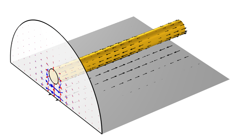
Arrow visualization of the current (black), electric field (red), and magnetic field (blue) at one instant in time.
It might be reasonable to ask: How can there be finite currents on the surface of a material with infinite conductivity? To answer this, we need to also look at the free space above the ground plane. This free space has an impedance, and currents flowing along this surface will see the impedance of this surrounding space.
This immediately raises a very important question: How much of the free space above the ground plane do we have to consider? It turns out that we have to consider the free space not only immediately above the ground plane but also the space around the wire, and even some region of space above the wire. All of this structure contributes to the impedance of the transmission line. In fact, when building a numerical model of such a case, it is necessary to study how much of the surrounding free space region to include; a point that is touched on in this example: Finding the Impedance of a Parallel Transmission Line.
So, this means that the currents on this perfect electric conductor surface (that we are calling a ground plane) are affected by everything above it. Another way of saying this is the currents on this PEC surface contain an image of the entire modeling space, and this leads us to a second interpretation of the PEC ground plane: It is a symmetry condition. It is as if there were an equivalent structure of the other side of the plane, and on that side, the currents on the line will be pointing in opposite directions.
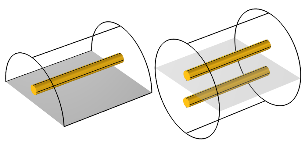
Via the symmetry condition, a model of a wire above a ground plane is equivalent to a model of a parallel-wire transmission line.
At this point, within the context of electromagnetic waves, we can now start to make some more precise definitions: A ground is a lossless (perfectly electrically conductive, or PEC) surface along which finite currents flow. The currents flowing along this surface will be affected by all of the structure above it. If this PEC surface describes a plane on one side of the modeling space, then it is equivalent to imposing a symmetry condition. If you have two PEC surfaces that are separated, you can arbitrarily choose one and define that as a ground. We can also, in some cases, come up with a way to define an electric potential difference (a voltage) of the second PEC surface relative to this ground.
Defining Voltage in the Frequency Domain
Recall from our discussion of steady-state electric currents that we defined voltage as the path integral of the electric field between any two points. For the steady-state case, the electric field is the gradient of a scalar potential, and this integral is always path independent. However, for the electromagnetic wave case, the electric field is the solution to a wave equation, and (via a tedious amount of vector calculus that we will skip) we can show that the path integral of such an electric field is not path independent, except for some special cases.
One of these special cases is when you take the path integral along a line lying on a PEC surface. The electric field tangent to the surface is always zero, and thus the integral of the electric field along any line on that surface is zero. However, the surface currents are defined as \mathbf{J = n \times H}, where \mathbf{ H} is computed from \mathbf{\nabla \times E} = -j \omega \mathbf{H}, so the currents are nonzero, even though the integral of the tangential electric field is zero. Keep in mind that there is no contradiction here; the impedance of the surroundings leads to finite currents on this PEC surface with zero tangential electric field.
The second interesting case to consider is when we take the path integral of the electric field along a line in a plane perpendicular to the axis of a TEM transmission line. Since, by definition, the electric and magnetic fields lie purely in this plane, it can be shown (via some more vector calculus that we will skip) that this integral will be path independent. That is, we can define a voltage between points in this plane. So, choose one point that lies on the surface we call ground, and on the other point on the wire of our transmission line, take any path integral. Now we have a voltage, and this corresponds to the measurement that you would get from a signal analyzer. You can also take the path integral of the magnetic field along a line that entirely divides the space between the ground and the wire, and this will give us the current flowing along the transmission line.
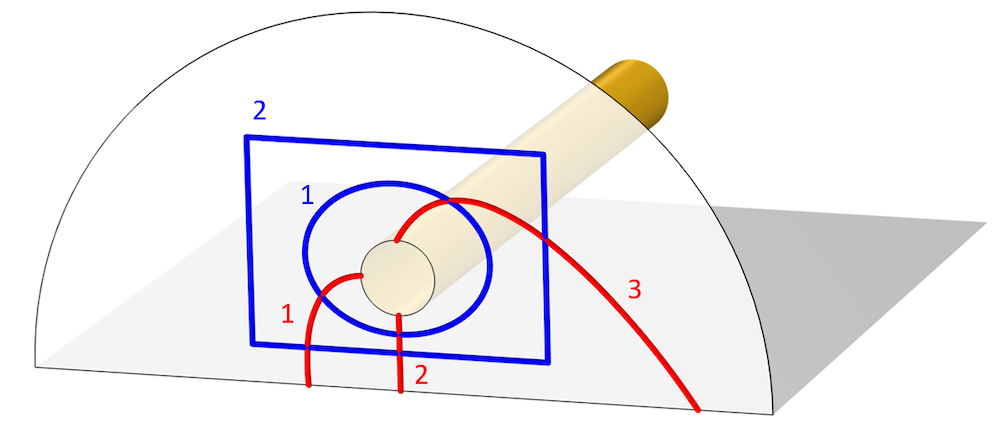
Image showing various different integration paths for voltage (red) and current (blue).
Finally, let’s address the fact that this is actually a quasi-TEM line, due to the finite conductivity of the wire, which can be modeled via the Impedance boundary condition. For this case, the out-of-plane components of the electric and magnetic fields are so small relative to the in-plane components that we can still safely use the aforementioned definitions.
So, let’s write down what we know:
- The voltage is the path integral of the electric field, but this can only be evaluated where the curl of the electric fields is zero, or nearly zero: at the cross section of a TEM or quasi-TEM transmission line.
- At the cross section of a TEM or quasi-TEM transmission line, the voltage corresponds to what you would physically measure via a signal analyzer. It is really only here that the term voltage has any useful meaning in a frequency-domain wave electromagnetics model.
- On a PEC surface, you can integrate the electric field along a path on that surface, but if you integrate along a path that is not on the surface, you might get a nonzero integral. Also, we’ve already seen that there will be currents, so zero voltage difference between two points does not mean zero current. Thus, in practice, there is little value to speaking about the voltage in this context. If we would try to actually physically measure the fields between two points, we would have to introduce a sensor, including some kind of transmission line between those points, which would alter the device.
With all of that information firmly in our minds, we can now model with confidence. For the case we have here, we can use the TEM-type Port boundary condition, with the Ground and Electric Potential subfeatures applied to the edges of the ground plane and wire. A complete overview of all of the other options for modeling TEM-type transmission lines is given in the Learning Center article “Modeling TEM and Quasi-TEM Transmission Lines“.
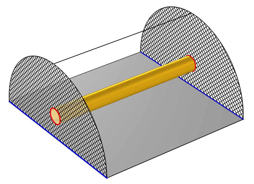
Schematic of the setup of a transmission line model. Two TEM ports (crosshatched) at either end have a ground (blue) and voltage (red) defined.
Closing Remarks
Now you know how to use the terms voltage and ground with confidence in the context of frequency-domain electromagnetics wave modeling. We can extend the same arguments to the transient case and arrive at the same conclusion: In time-domain modeling, the ground is a current return path that can be a symmetry condition.
So, for the case of any time-varying model where we consider both electric and magnetic fields, you can only speak about voltage in the context of evaluating the fields at the cross section of a TEM transmission line. In spite of the simplicity of this statement, the arguments that we had to follow to get to this point are very helpful in understanding modeling of electromagnetic devices.
Next Step
Get a detailed demonstration of modeling TEM and quasi-TEM transmission lines in a related Learning Center article, which includes step-by-step modeling instructions and software screenshots, by clicking the button below:


Comments (0)