Aggiornamenti Design Module
Per gli utenti del Design Module, la versione 6.3 di COMSOL Multiphysics® introduce diversi miglioramenti per una gestione più efficiente della geometria. Questi aggiornamenti includono il supporto dei più recenti formati di file CAD, la possibilità di visualizzare in anteprima gli alberi di assiemi per l'importazione selettiva dei componenti e la pulizia automatica della geometria per la preparazione delle mesh. Inoltre, lo strumento Detect Interferences è stato aggiornato per offrire un migliore rilevamento degli spazi vuoti con una tolleranza personalizzabile, ci sono nuove opzioni per i raggi di raccordo a raggio variabile e a larghezza costante e una nuova funzione per proiettare i lati sulle facce. Per scoprire di più su questi aggiornamenti, continuate a leggere.
Raggi di raccordo variabili e a larghezza costante
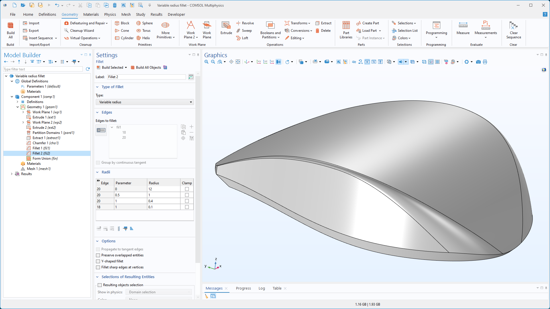
La funzione Fillet offre ora due nuove opzioni per una maggiore flessibilità nell'arrotondamento dei lati degli oggetti 3D. L'opzione Variable Radius può essere utilizzata per specificare raggi che variano in modo uniforme tramite interpolazione in più punti lungo una catena di bordi. L'opzione Constant Width consente di definire una larghezza fissa per la faccia del raggio di raccordo, assicurando che la larghezza rimanga coerente lungo l'intero spigolo raccordato.

Funzione Project to Faces
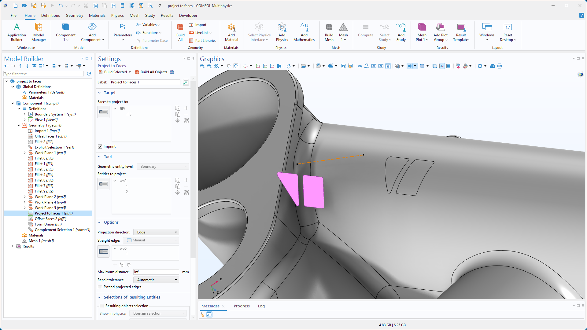
La nuova funzione Project to Faces consente di proiettare i lati sulle facce con vari metodi di proiezione. I lati possono essere proiettati lungo un lato esistente, nella direzione di un vettore specificato o perpendicolarmente alle facce di destinazione. È inoltre disponibile la proiezione prospettica, in cui un punto esistente può essere scelto come posizione dell'occhio per la proiezione.

Updated CAD File Import
The CAD file import functionality now supports the latest versions of all compatible file formats. Additionally, AutoCAD®, Inventor®, e SOLIDWORKS® files can now be imported on supported Linux® operating systems with Intel® 64-bit processors. For a complete list of supported CAD file formats, visit the Read from File, CAD section of the CAD specification chart.
Preview the Assembly Tree of CAD Assemblies
When importing CAD assemblies in the Inventor®, NX™, PTC Creo Parametric™, PTC Pro/ENGINEER®, e SOLIDWORKS® file format, it is now possible to preview the assembly tree, enabling users to select specific components to import from the assembly.
Updates to the Detect Interferences Tool
The Detect Interferences tool now enables specification of a separate gap tolerance, improving the detection of gaps while simultaneously searching for other types of interferences. Additionally, new options have been added to select which types of detected interferences to display in the Interfering Faces list. These options include Show intersections, Show touches, Show gaps, and Show containments.

Automatic Geometry Cleanup
Small details and gaps in geometry can now be automatically detected and removed, simplifying the geometry for meshing purposes and reducing simulation size. The automatic process identifies small features like sliver faces, short edges, narrow gaps, and thin domains, which are then removed to prepare the model for analysis. For more control, the optional Cleanup Wizard makes it possible to adjust detail sizes and select cleanup operations.
The Geometry Cleanup functionality can automatically modify Boolean tolerances, add a Remove Details operation, and leverage functionality in the CAD Import Module or Design Module, depending on the detected features and available licenses. The Geometry Cleanup functionality is demonstrated in the Electrical Heating in a Busbar Assembly, Geometry Cleanup on a Wheel Rim Geometry, and Importing and Meshing a PCB Geometry from an ODB++ Archive tutorial models. Note that the more advanced features of the Geometry Cleanup functionality require a license for the CAD Import Module, Design Module, or one of the LiveLink™ products for CAD. For more details, see the CAD Specification Chart.
Virtual Operations
The virtual operations toolkit now includes the Merge Faces operation, which merges faces and eliminates gaps or regions between selected surfaces. When using the CAD Import Module, Design Module, or one of the LiveLink™ products for CAD, the operation can also merge faces of different sizes and shapes by automatically creating the necessary imprints. The Merge Faces operation is also integrated into the new Geometry Cleanup process.
Nuovi tutorial
La versione 6.3 di COMSOL Multiphysics® introduce due nuovi tutorial nel Design Module.
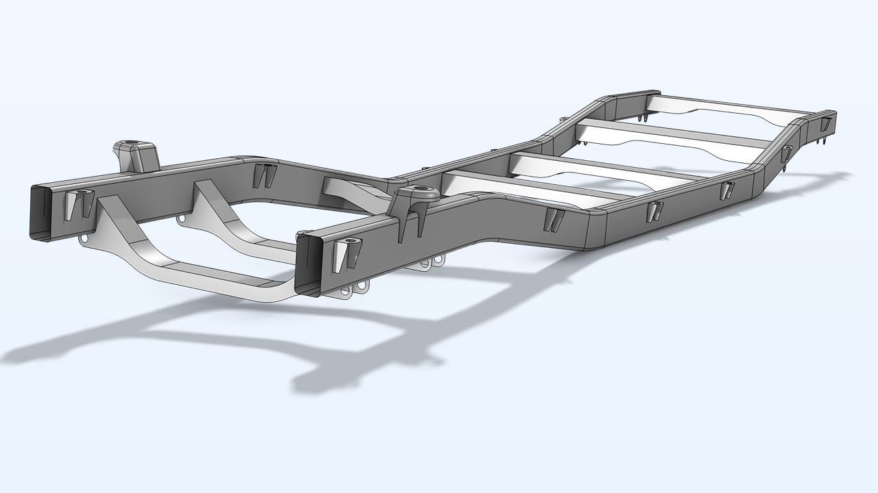
Ladder Frame Geometry

Titolo in Application Library:
ladder_frame_geometry
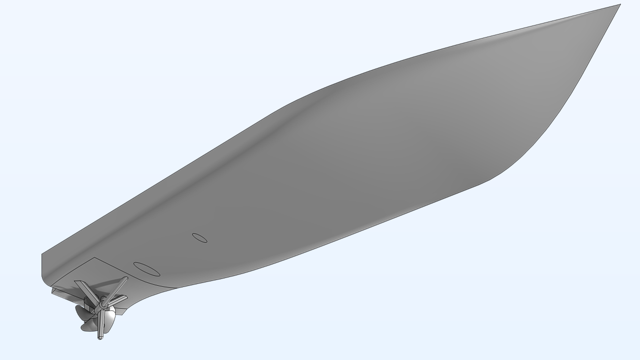
Ship Hull Geometry
Titolo in Application Library:
ship_hull_geometry
Autodesk, il logo Autodesk, AutoCAD e Inventor sono marchi registrati o marchi di Autodesk, Inc. e/o delle sue consociate e/o affiliate negli Stati Uniti e/o in altri Paesi. Intel è un marchio di Intel Corporation negli Stati Uniti e/o in altri Paesi. Linux è un marchio registrato di Linus Torvalds negli Stati Uniti e in altri Paesi. NX è un marchio o un marchio registrato di Siemens Product Lifecycle Management Software Inc. o delle sue consociate negli Stati Uniti e in altri Paesi. PTC, Creo, Creo Parametric e Pro/ENGINEER sono marchi o marchi registrati di PTC Inc. o delle sue consociate negli Stati Uniti e in altri Paesi. SOLIDWORKS è un marchio registrato di Dassault Systèmes SolidWorks Corp. Il supporto per l'implementazione del formato ODB++ è stato fornito da Mentor Graphics Corporation in base ai Termini e condizioni generali della ODB++ Solutions Development Partnership (https://odbplusplus.com/design/terms-of-use/).


