Aggiornamenti ECAD Import Module
Importazione dei contorni dei componenti per l'importazione di PCB
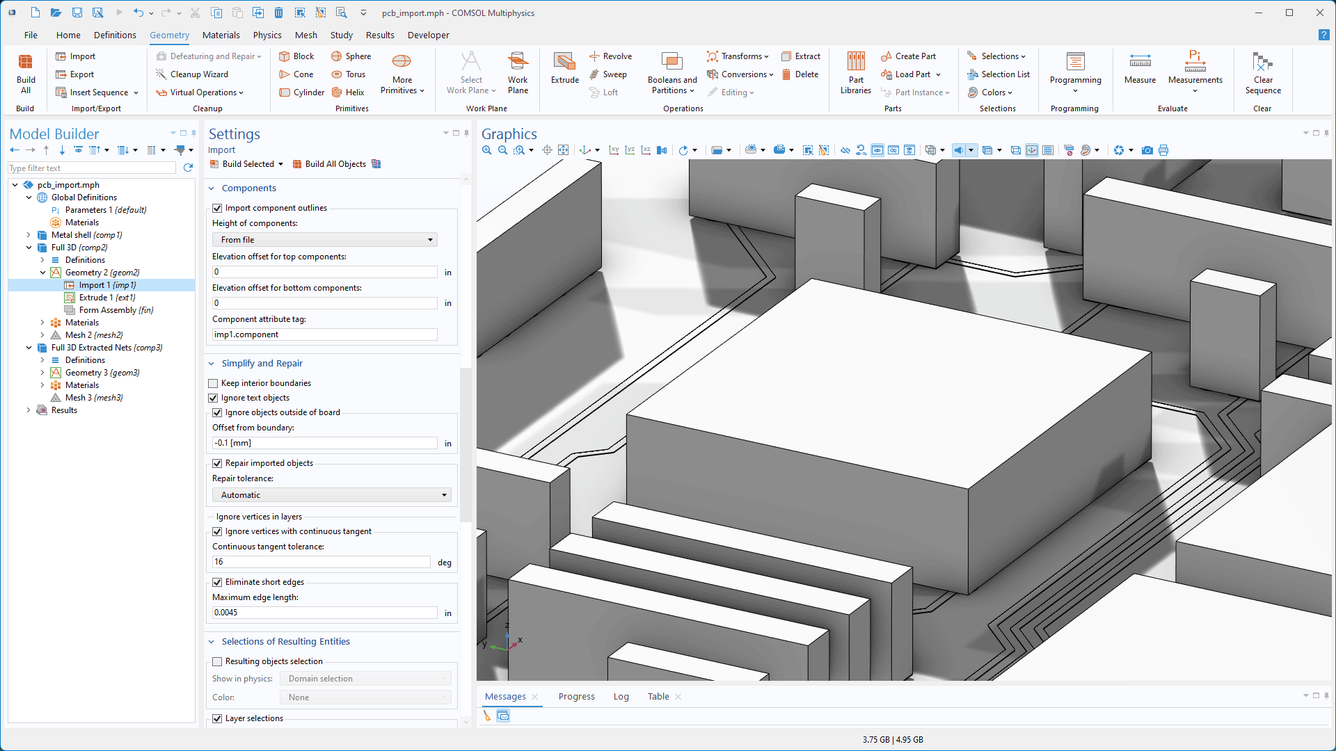
Quando si importano file IPC-2581 e ODB++ nella versione 6.3 di COMSOL Multiphysics®, è possibile generare geometrie semplificate dei componenti in base ai contorni dei componenti presenti nei file. I componenti possono essere rappresentati come facce planari o estrusi utilizzando le informazioni sull'altezza contenute nel file. Ai componenti generati vengono assegnati automaticamente degli attributi per facilitarne l'identificazione in base ai nomi e ai tipi di pacchetto. Con la nuova funzione Logical Expression Selection, gli attributi possono essere utilizzati nelle espressioni per creare selezioni.

Creazione di vias placcati
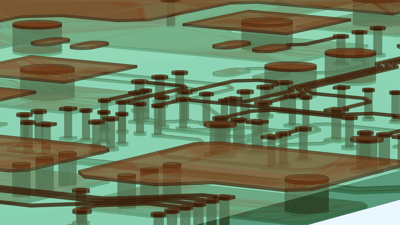
Le impostazioni per l'importazione di file IPC-2581 e ODB++ includono ora un campo Plating thickness, che consente di creare domini per vias e fori placcati con uno spessore di placcatura di rame specificato. Ulteriori opzioni consentono di decidere se creare domini di anime per diversi tipi di fori, tra cui vias, fori placcati e fori non placcati.
Importazione di PCB migliorata per un'impostazione più efficiente della simulazione in 3D
Le nuove opzioni predefinite per l'importazione di file IPC-2581 e ODB++ consentono di creare una geometria di scheda 3D adatta alla simulazione in un solo passaggio. Il processo di importazione unisce le regioni di rame e dielettrico, integra vias e fori come domini o vuoti e genera automaticamente le selezioni per le regioni di rame e dielettrico per facilitare l'assegnazione dei materiali e della fisica. Questi miglioramenti snelliscono il flusso di lavoro, eliminando la necessità di operazioni booleane e di selezione manuali e preparando la geometria per la meshatura swept con il metodo Form Assembly. Il tutorial Importing and Meshing a PCB Geometry from an ODB++ Archive è stato aggiornato per illustrare questi miglioramenti.

Esportazione nel formato OASIS
Con la versione 6.3 di COMSOL Multiphysics®, i progetti possono ora essere esportati direttamente nel formato OASIS, uno standard ampiamente utilizzato per lo scambio di progetti di fotomaschere. Questa nuova funzionalità semplifica i flussi di lavoro eliminando la necessità di una fase di traduzione separata quando si inviano i prototipi alla produzione. La funzione di esportazione supporta sia le geometrie 2D che quelle 3D. Per le esportazioni 3D, gli utenti possono selezionare i piani di lavoro da salvare come livelli in un file OASIS.
Il supporto per l'implementazione del formato ODB++ è stato fornito da Mentor Graphics Corporation in base ai termini e alle condizioni generali della ODB++ Solutions Development Partnership.
